When profile tolerance is used with datums, it can control the form, size, orientation and position of the surface. The virtual envelope that gets created by the profile tolerances is called the profile tolerance zone.
What is profile tolerance?
What is the tolerance zone of a profile?
What is the virtual envelope that gets created by the profile tolerances?
What is bilateral unequal profile tolerance?
How to measure simple profile tolerance?
When is the tolerance zone of a profile spread across both sides of the true profile?
What industries use profile tolerance?
See 2 more
What does a profile tolerance control?
Profile is a complex tolerance that simultaneously controls a feature's form, size, orientation, and sometimes location. Profile is a three-dimensional tolerance that applies in all directions regardless of the drawing view where the tolerance is specified.
What does profile of a surface control?
0:011:27GD&T Profile of a Surface (Basics) - YouTubeYouTubeStart of suggested clipEnd of suggested clipControls are both profiles. These include profile of a line and profile of a surface. We'll firstMoreControls are both profiles. These include profile of a line and profile of a surface. We'll first look at profile of a surface. As it is the most common of the two and likely what you'll use profile
Does profile control flatness?
One of the places that profile is often used to control flatness is when flatness must be controlled on multiple surfaces. Flatness can only be applied to one surface at a time unless the Continuous Feature symbol is used to indicate that the two surfaces must be considered to be one surface.
What type of tolerance is positional tolerance?
Position is a 2D/3D tolerance in GD&T that defines tolerance zones depending on the feature. For cylindrical features, it creates a cylindrical tolerance zone around the true position of the feature within which the axis of the feature must lie for all manufactured products.
Why are profile control tolerances used in GD&T?
The 'profile of a surface' (sometimes simply 'surface profile') control is used in GD&T (geometric dimensioning & tolerancing) to control the form of any 2D surface in 3D space. It is one of the most powerful GD&T controls and can be used with complex freeform geometries.
What can a profile control be applied to?
It can be used to control the size, location, orientation, and form of a part feature. Profile of a surface or line can be used to tolerance planar surfaces, cylinders, cones, curves, and irregular curves. When a profile of a surface control is specified, the tolerance zone is a uniform boundary (a 3-D tolerance zone).
Does profile of a surface control location?
When used with datums it can control every aspect of a feature's geometry which includes size, location, orientation, and form. Profile of a surface can be used for advanced curved surfaces, such as when a surface curves in multiple axes at once.
Can you have a profile tolerance without a datum?
When used without a datum, the profile of a surface can replace all the form controls. These form controls constrain the form of a part by creating a tolerance zone between two parallel surfaces. These planes can be either flat or cylindrical.
Can MMC be applied to profile?
RE: Profile and MMC You cannot use the MMC modifier in the tolerance compartment of the feature control frame. When a profile tolerance is applied with no datum references it is solely a form control. The actual size of the feature must be specified in some other manner, which then bounds the overall size.
What are the 3 types of tolerances?
These are grouped into form tolerance, orientation tolerance, location tolerance, and run-out tolerance, which can be used to indicate all shapes.
What is meant by positional tolerance?
Position Tolerance (symbol: ⌖) is a geometric dimensioning and tolerancing (GD&T) location control used on engineering drawings to specify desired location, as well as allowed deviation to the position of a feature on a part.
How do you position tolerance?
Steps to measure & calculate Position Tolerance with LMC: I.e. Deviation in X is 0.15 and the increase in diameter is 0.15. Use the following formula to calculate radial hypotenuse value Multiply by 2 for the diametrical position tolerance. Diametrical Actual Tolerance = 2 X under root (0.15) square + (0.00) square.
What does profile of a surface mean?
Description: Profile of a surface describes a 3-Dimensional tolerance zone around a surface, usually which is an advanced curve or shape. If it is called out on a curved surface, like a fillet on a welded part, the entire surface where the radius is has to fall within the tolerance zone.
What does surface profiling mean?
Introduction. Surface profile is defined as a measurement of the maximum peak-to-valley depth generated by abrasive blast cleaning and impact-type power tools. These operations effectively increase the surface area and provide an “anchor” for the applied coating system.
What is profile of a surface symbol?
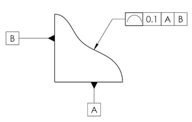
The profile of a surface symbol is a half-circle with the curved edge facing up and the flat edge on the bottom. On the feature control frame, the box to the right of the Profile of a Surface symbol contains the tolerance for the surface.
What is profile in surface roughness?
Profile surface roughness is a parameter that strongly depends on the reaction/corrosion occurring at the surface. Profile surface roughness can be expressed either as average surface roughness (Ra) or as root mean square surface roughness (Rq). Both are the measure of the fluctuations on the surface of a material.
Profile of a Surface – Unilateral vs. Bilateral | GD&T Basics
Figure 3: Phantom Line Method for Unilateral Tolerance Zone. Using the Phantom Line method, the tolerance zone’s upper and lower boundaries are shown on the drawing using phantom lines. The feature control frame is the same as that for a Bilateral tolerance zone, with the total tolerance shown.
What is tolerance zone?
The tolerance zone is a tube-shaped shell 1.0 mm thick, straddling the nominal surface of the hole. The OD of the tube will be the hole's basic diameter plus 0.5 mm, and the ID of the tube will be the basic diameter minus 0.5 mm.
How to legitimize the use of a hard attribute gauge?
The only way to legitimize the use of a hard attribute gauge would be to divvy the profile tolerance into proportions for size and position @ MMC and then employ an attribute process sampling strategy which means enormous sample sizes to detect "goal post" conformity. Also divvying up the profile tolerance so that an LMC hole and its maximum position deviation is equivalent to the LMB (least material boundary) of the profile tolerance means that the separate tolerances have to be reduced which may force subsequent machining (not feasible for "as cast") and cost more .
What controls the size, form, orientation and location of a hole?
In this case, the profile zone controls the size, form, orientation and location of the hole.
Is a profile boundary easier to verify than a size and position boundary?
In so many cases, a profile boundary that effectively controls the functional limits (as pointed out above, not the exact equivalent of the size & MMC position boundary) is far easier to verify than separate size & position controls. I haven't come across an example yet where using a surface profile in place of size & MMC tolerance cost more or was more difficult to verify. On the otherhand, some people want SPC data and aren't adequately familiar with their CMM or digital inspection equipment software to draw the data out of a profile inspection protocol. Don't just shy away from profile because you aren't well versed in it. Take the step to get better versed & gain the value of profile controls.
Is an attribute gauge appropriate for a surface?
An attribute gauge on profile of a surface is not appropriate since it only covers outer boundary and not perpendicularity to datum A or straightness on the "Z" axis. The best method with a profile of a line or surface is the use of CMM and plotted points covering all the requirements. Dave D.
Can you apply a zero tolerance to a hole?
I like to apply to holes zero positional tolerances at MMC. An alternative to this would be to apply a unilateral profile tolerance with the guide line outside the hole. See Figure 6.5.1 in the standard.
What is profile tolerance?
1. The Profile tolerance controls the form and size of the pocket, and its orientation relative to A.
Can you specify RFS and profile together?
It would not make sense to specify Profile and Position RFS together. It has to be MMC (or LMC) to define a virtual condition, as you say. Actually, the Y14.5 term would be Positional Boundary.
What is tolerance of position?
Tolerance Of Position is a geometric control that specifies how far away from True Position a feature of size is allowed to be. Tolerance Of Position has some fundamental rules: 1. Tolerance Of Position must always be applied to a Feature of Size. 2. Tolerance Of Position must always be located by Basic Dimensions .
What is the red tolerance zone?
The bottom line holds the center planes of both windows within the red tolerance zone. The red tolerance zone is two parallel planes that are 0.2 apart. This tolerance zone is exactly parallel to datum [A], but this tolerance zone is allowed to float within the 0.5 tolerance zone.
What is the maximum bonus tolerance?
The maximum bonus tolerance allowed is when the hole is at its largest allowable size. Therefore the maximum bonus tolerance allowed is always equal to the size tolerance. Now consider the case when the hole is centered but tilted. The tolerance of position limits the amount that the hole can tilt.
Where is the tolerance cylinder on a bolt?
On the left, the tolerance cylinder is inside the part . The bolt centers itself on the threads in the threaded hole. As the bolt extends through the cover while tilted as much as the tolerance of position will allow, there is a conflict between the bolt and the side of the clearance hole in the cover.
Is tolerance of position the same as perpendicularity?
The Tolerance Of Position specifies exactly the same boundary. Again, this boundary is perpendicular to [A] but not located to any datums. So once again the Perpendicularity and the Tolerance of Position have exactly the same meaning.
Does tolerance of position have a datum?
Tolerance Of Position must always have one or more datum references except for two exceptions: Coaxial cylinders and a pattern of features of size used as a primary datum. The figure below shows the two cases in which a Tolerance Of Position does not require a datum reference.
Can windows rotate in tolerance zone?
Since each window could be at the opposite end of the tolerance zone, the windows could be offset from each other. The windows can also rotate relative to datum [A] and relative to each other.
What is a 3 dimension tolerance zone?
3-Dimensional tolerance zone existing of 2 parallel surface curves that follow the contour of the surface profile across the entire length of the surface. This tolerance zone may or may not be referenced by a datum.
What is a datumless profile control?
A profile control without any datums attached to it is a form control. This means that the profile tolerance has to be tighter than the size tolerance due to Rule #1 and serves to refine the surface. Think of a datumless profile control as restricting the smoothness of the face/surface.
What is a profile on a surface?
Profile of a surface describes a 3-Dimensional tolerance zone around a surface, usually which is an advanced curve or shape. If it is called out on a curved surface, like a fillet on a welded part, the entire surface where the radius is has to fall within the tolerance zone. Profile controls all the points along the surface within a tolerance range that directly mimics the designed profile. Any point on the surface would not be able to vary inside or outside by more than the surface profile tolerance. Usually, when surface profile is required, there are no tolerances on the dimensions that describe the surface and use the GD&T callout to give the acceptable range.
What is profile in datums?
When used with datums, profile can mimic all the orientation symbols (perpendicularity, parallelism, angularity) and even control the location and size of a feature or surface. All of these tolerance symbols specify how much a surface of any geometric shape can vary from its true form.
Is VL or CMM better for inspection?
Some controls and drawing requirements are better suited to a specific method, but there is no end-all be-all solution. CMM is, in general, a fast, easy and cost effective way of doing inspections.
Is line tolerance tighter than surface tolerance?
Sometimes profile of a line is used in conjunction with profile of a surface. In these cases, the line profile tolerance will be tighter than the surface tolerance. This ensures that along any specific cross-section of the profile, the part will be tightly controlled, while at a looser extent, the total profile is also controlled.
Why don't you use profile?
And you wouldn’t use profile, because form control is not needed! Second, though the minimalist philosophy seeks to simplify drawings, it can actually make it harder for people to decipher what you are trying to say.
Can position and profile control multiple qualities?
So the bottom line is: While it is possible — and often desirable — to use position and profile to control multiple qualities of a feature, we shouldn’t ignore the other symbols, which have a definite role to play in the GD&T world.
Do GD and T overlap?
There is some logic to what these people are saying — namely, that many GD&T symbols overlap others, and position and profile can be used in such a way as to cover the others. But as you might guess, there are pros and cons to this.
What is a position tolerance?
The Position tolerance is the GD&T symbol and tolerance of location. The True Position is the exact coordinate, or location defined by basic dimensions or other means that represents the nominal value. In other words, the GD&T "Position" Tolerance is how far your feature's location can vary from its "True Position".
What is the tolerance of a plane?
The tolerance is a 2 or 3-Dimensional tolerance zone that surrounds the true location where a feature must lie. Usually, when specifying true position, a datum is referenced with x and y coordinates that are basic dimensions (do not have tolerances). This means that you will have an exact point where the position should be and your tolerance specifies how far from this you can be. The location is most often positioned with two or three datums to exactly locate the reference position. The true position is usually called out as a diameter to represent a circular or cylindrical tolerance zone. (However, it can also be called out as a distance for X and Y coordinates as well – see final notes)
How to determine true position of a feature?
True position of a feature is made by first determining the current referenced point and then comparing that to any datum surfaces to determine how far off this true center the feature is . It is simplified like a dimensional tolerance but can be applied to a diameter tolerance zone instead of simple X-Y coordinates. This is done on a CMM or other measurement devices.
What is functional gauge in MMC?
With an MMC callout you now can use a functional gauge to measure this part, to determine that the size and geometric tolerancing are within spec at the same time .
What is the true position of a GD&T symbol?
The Position tolerance is the GD&T symbol and tolerance of location. The True Position is the exact coordinate, or location defined by basic dimensions or other means that represents the nominal value. In other words, the GD&T “Position” Tolerance is how ...
What is a 2-dimensional cylindrical zone?
A 2-dimensional cylindrical zone or, more commonly a 3-Dimensional cylinder, centered at the true position location referenced by the datums.
What is position in GD&T?
Position can be used on any feature of size (but not on surfaces where we would use Profile ). Position is probably the most widely used symbol in GD&T. If you are looking for more information about Position or any of the other symbols, you should check out our GD&T Fundamentals Course.
How to measure position control tolerance?
After measuring the actual position of the feature it is compared with the true position. Any variation in the feature location should be within limits.
What is Position Control Tolerance in GD&T?
GD&T Position tolerance controls the variation in the location of a feature from its true position. We can use MMC, LMC, Projected tolerance modifiers to define the true position of a feature. Here a feature can be a hole, slot, or pin.
What are the two datum planes used for position control?
Two or three datum planes are required to specify position control. Material Condition (MMC and LMC), Projected Tolerance, Tangent Planes can be used. Generally, diameter symbols are used to make circular or cylindrical tolerance zones.
What is profile tolerance?
Profile tolerance is the amount of deviation of a profile of a line or a surface. No surface can be made absolutely perfect. Due to machine or measurement variations, engineers should allow a deviation in the line elements or surfaces called profile tolerance.
What is the tolerance zone of a profile?
When the tolerance zone of a profile is in one direction, it is called Unilateral profile tolerance . See the below example where the profile tolerance is only in one direction. It can also be in the opposite direction, but it can not be in both directions.
What is the virtual envelope that gets created by the profile tolerances?
The virtual envelope that gets created by the profile tolerances is called the profile tolerance zone. In the below example, the envelope formed by the blue surfaces is called the profile tolerance zone.
What is bilateral unequal profile tolerance?
When the profile tolerance is unequally distributed on both sides , it is called bilateral unequal profile tolerance. In the below picture, what the profile tolerance means is that the total profile tolerance is .003. Out of that, .002 is on the outside of the true profile. Whatever is showing after the ” U” modifier is the offset of the outside surface.
How to measure simple profile tolerance?
Simple profile tolerance can be measured using height gauge. Complex profile uses CMM to measure
When is the tolerance zone of a profile spread across both sides of the true profile?
When the tolerance zone of a profile is spread across both sides of the true profile, it is called bilateral profile tolerance . In the feature control frame, we need to use a ” U ” modifier symbol which shows how much deviation is allowable outside of the true profile. The “ U “ symbol is only required when there is unequal bilateral tolerance.
What industries use profile tolerance?
Profile tolerance is beneficial in industries like automobiles and aerospace as these industries use complex shape parts. But that does not mean that only these two industry uses profile tolerance. Now a day profile tolerance is used in almost every industry.