How do i connect ftdi to arduino?
- Connect the Black (Ground) wire to the ground of your chip.
- Connect the Red (VCC) wire to the power/VCC/5V pin of your chip.
- Connect the White (DTR) wire to the Reset pin.
- Connect the Orange (TX) wire to SCK pin (Arduino pin 13)
- Connect the Blue (CTS) wire to the MISO pin (Arduino pin 12)
- Connect the Black (Ground) wire to the ground of your chip.
- Connect the Red (VCC) wire to the power/VCC/5V pin of your chip.
- Connect the White (DTR) wire to the Reset pin.
- Connect the Orange (TX) wire to SCK pin (Arduino pin 13)
- Connect the Blue (CTS) wire to the MISO pin (Arduino pin 12)
What do I need to make a FTDI cable for Arduino?
It plugs in to the RX, TX, Reset, 5V, and GND pins on the Arduino and has a 6 pin female header for the FTDI connection. This can most likely be made with electronics supplies you already have. Not much is needed at all for this. The only materials you need are: Solder your 5 cables to the header.
Where do I plug in the FTDI connector?
It plugs in to the RX, TX, Reset, 5V, and GND pins on the Arduino and has a 6 pin female header for the FTDI connection. This can most likely be made with electronics supplies you already have.
How do you connect TX and RX pins to Arduino?
On the 2 pin header (the other part of the 4 pin), solder the left pin to TX and the right pin to RX. You are ready to connect! Plug in your 4 pin header into the bottom-left row of pins on the Arduino. Next, connect the TX/RX pins to 0/1 respectively. On the other side, connect your FTDI header to your device.
How do I connect a 4-pin header to an Arduino?
Plug in your 4 pin header into the bottom-left row of pins on the Arduino. Next, connect the TX/RX pins to 0/1 respectively. On the other side, connect your FTDI header to your device. To upload something, just upload as you usually would to your Arduino, but select your target board instead of the Arduino you are using.
How do I program FTDI with Arduino?
Program Arduino Mini 05 With FTDI BasicStep 1: Materials. Arduino Mini. FTDI Basic. ... Step 2: Prep Arduino. You only need to connect to four pins of the Mini in order to program it. ... Step 3: Connect. The connections to make from the FTDI board and the Mini are: ... Step 4: Upload Sketch. Open the Arduino environment, go to:
How do I connect to FTDI?
FTDI Driver Installation Now plug USB cable with your laptop or computer. Next step is to install drivers for FTDI chip. On latest operating systems, such as Windows 10 or Linux Ubuntu, device drivers will be installed automatically when you plug USB into computer.
What is FTDI in Arduino?
An "FTDI chip" usually refers to one of the USB to serial chips from FTDI. FTDI also makes other parts that aren't USB to serial, but their USB to serial chips are quite ubiquitous and are used on many development boards, including the Arduino board.
How do I program ATmega328 with FTDI?
Programming an ATmega328 with Arduino bootloader via a FTDI USB-serial adapterConnect the DTR pin to pin 1 on the ATmega through the 0.1uF capacitor.Connect the RX pin to pin 3 on the ATmega (TX)Connect the TX pin to pin 2 on the ATmega (RX)More items...•
How do I know if FTDI is working?
In Device Manager, expand Ports (COM & LPT) and select your serial port. The port number may not match what is shown here. Double-click the serial port and the USB Serial Port Properties dialog will appear. Go to the General tab and verify that the manufacturer is FTDI.
What is FTDI connector?
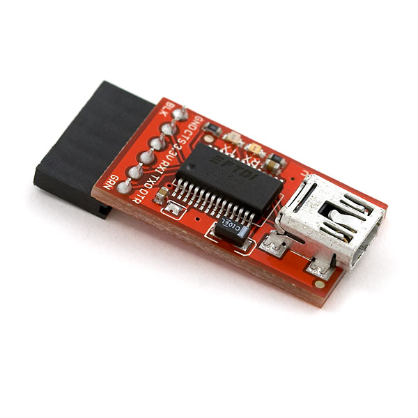
The FTDI cable is a USB to Serial (TTL level) converter which allows for a simple way to connect TTL interface devices to USB. The I/O pins of this FTDI cable are configured to operate at 5V. The FTDI cable is designed around an FT232RQ, which is housed in a USB A connector.
Does Arduino Uno have FTDI?
Thanks in advance for any support. The Uno has an Atmega328P on it which talks serial. The FTDI converts serial to USB and vice versa. If you have a com port on your computer you could in theory just connect straight to the Atmega 328P provided the voltage levels are TTL rather that proper RS232.
Why do we need FTDI?
The major application of the FTDI module is for interfacing in serial communications, mostly as USB and serial TTL interfacing. Communication through the microcontroller development boards such as ESP-01s and Arduino is the most popular application of the FTDI module because they do not have an in-built USB interface.
What is FTDI USB chip?
FTDI Chip offer a wide range of USB based converter cables offering a variety of connectivity options. Connectivity options include conversion from USB to RS232, RS422, or RS485 interfaces, and TTL based signaling interfaces.
How do I upload a Ftdi code?
3:404:40Arduino IDE : Using FTDI (Upload Sketch to Mini and LilyPad)YouTubeStart of suggested clipEnd of suggested clipAfter this rest is same connect the FTDI to the pc using a mini USB cable. Select lilypad from theMoreAfter this rest is same connect the FTDI to the pc using a mini USB cable. Select lilypad from the board selector. Select the port and then just upload the sketch and you're ready to go.
Can I program ATmega328P with Arduino?
Luckily, if you have an Arduino, you already have what you need since the Arduino itself can be used as a programmer for the ATmega328P (and many other AVR microcontrollers). This article shows how to program a standalone ATmega328P using an Arduino and the Arduino IDE.
What is FTDI module?
FTDI Chip offers a complete range of PCB boards and sub-assemblies based around FTDI chips. The modules are available in a range of formats to support various applications, including: development, pre-production, and in some cases end-product integration.
How do I connect my laptop to FTDI?
0:033:17FTDI Chip UART to USB Solutions - YouTubeYouTubeStart of suggested clipEnd of suggested clipWith the laptop connected to the internet. It's just a case of plug. And play when you connect theMoreWith the laptop connected to the internet. It's just a case of plug. And play when you connect the cable. The driver wizard will start and the driver will install.
How do I fix the USB FTDI problem?
This guide followed step by step will completely fix the driver problem thus making your board working again.Step 1: check if you have a faulty ftdi chip driver. ... Step 2: modify values. ... Step 3: download the 2.10.0.0 ftdi driver. ... Step 4: connect your arduino board. ... Step 5: modify the chip eeprom.
How do I install FTDI drivers on Windows?
How to Install FTDI DriversPlug in your FTDI using a USB cable. ... Navigate to the FTDI website, and choose the 'VCP' (Virtual Com Port) option near the bottom.Now choose either the 32 bit version or the 64 bit version. ... Open the start menu, right-click on 'Computer,' and left-click on 'Properties'.More items...
How do I connect to UART?
Connecting Multiple UART Devices: You can either attach the devices with a single cable that encompasses all TXD, RXD, CTS, RTS and other pins or you can attach individual jumper wires to each of these significant individual pins and connect them between the two devices.
Step 1: Materials
Not much is needed at all for this. The only materials you need are: -5 Wires -6 Pin Female Header -6 Male Header Pins, broken into sections of 4 and 2 -Solder -Electrical Tape And the only tools you need are: -Soldering Iron -Wire cutters -Hemostats help a lot with holding the wire in place -Fine Tip Permanent Marker
Step 2: Soldering: Part I
Solder your 5 cables to the header. I used red cables for the data and white for everything else. On the leftmost (or rightmost if you're turned the other way) side, connect the ground wire to both of the terminals on the end. Once you're done, wrap in electric tape and label it with the marker. Make sure to keep the cables aligned.
Step 3: Soldering: Part II
Now it's time to solder the other side. On the leftmost pin of the 4 pin male header (the one that was broken off of the 6 pin header) connect the RTS wire. This will be the reset pin on the Arduino. Skip the second-leftmost terminal and solder the third pin to VCC.
Step 4: Finish Line
You are ready to connect! Plug in your 4 pin header into the bottom-left row of pins on the Arduino. Next, connect the TX/RX pins to 0/1 respectively. On the other side, connect your FTDI header to your device. To upload something, just upload as you usually would to your Arduino, but select your target board instead of the Arduino you are using.
Step 1: Get the Hardware Required
Hardware Required 1-arduino Duemilanove, Diecimila or Nano 1-6 pin female header 6-jumper wires
Step 2: Wire It Up (5v Boards)
First you should remove the micro controller from the board you don't want to program or else you will be programing both micro controllers. Next connect jumper wires between the Arduino and header as shown in the photo below. Then go to the next step to program the Arduino.
Step 3: Program the Arduino
Now using your computer open up the Arduino software. Then connect your 2 Arduino's together and to your computer. Next go to tools and select the board you want to program After that if you want to test it out you can copy and paste all the text between the //.
What capacitor to use for reset on Arduino?
What you should be able to do is connect RTS to Reset on the board, using a 0.1 µF capacitor (in series). I found in practice that this did not bring Reset low enough to trigger it - I'm not sure why, except maybe the board has a stronger pull-up resistor on /RESET than expected. That technique works for me on breadboard Arduinos.
How many wires do I need to connect to a bootloader?
If you have a bootloader, you just need to connect up four wires from the FTDI cable:
What is the meaning of "back up"?
Making statements based on opinion; back them up with references or personal experience.
What jumper cables are used for GND?
In all my tutorials, you will find that I use Black Jumper cables for GND and RED jumpers for +ve voltage – unless specified otherwise.
What is a capacitor used for?
There are 2 kinds of capacitors that are most familiar, the electrolytic and the ceramic. What you have here are 3 ceramic capacitors. They are used literally everywhere. In TVs, laptops, as means to delay switches on lamps of large factories etc. etc. BUT mostly small value capacitors are used to FILTER electricity passing through the boards.
What socket do you use to solder an IC?
One thing that you should never ever forget if you are planning to solder this baby, you need to use a 28 DIP socket. I’ve seen amateurs solder the IC directly to their PCBs without using any kind of socketing. While some people may argue that this is not so wrong, look at it this way:
Where is the black GND on a IC?
TOP horizontal rail, where the BLACK GND is located (there's only 1 left). Connect it to pin 7 of the IC.
What are the two types of capacitors?
There are 2 kinds of capacitors that are most familiar, the electrolytic and the ceramic. What you have here are 3 ceramic capacitors. They are used literally everywhere.
How many pins are needed to connect an IC to an oscillator?
From the right lower side of the IC, count 6 pins, or DIPs if you prefer, and then add 1x jumper. Connect the other side of the jumper to the left side of the oscillator crystal.
Where is the resistor pin on a IC?
Moving on the 3rd from RIGHT RED jumper. Connect this on pin 5 of the IC (starting from the top right side). That is the pin where you have added the resistor
