How do you build a pneumatic system?
1:474:34Build a DIY Air Pressure Powered STEM Project for Kids - YouTubeYouTubeStart of suggested clipEnd of suggested clipSystem first fill up one of the syringes with air. And then attach it to a small piece of tubing.MoreSystem first fill up one of the syringes with air. And then attach it to a small piece of tubing. Make sure the other syringe is empty of air and attach that to the other end of the tubing.
What is pneumatic schematic diagram?
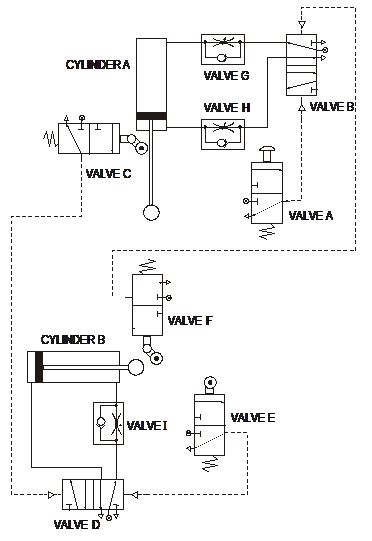
In pneumatic circuit diagrams, the components are arranged the way that the flow of energy always flows from the bottom up (as opposed to electrical schematics). Thus the pressure source represents the first element, the actuator, the last element.
How do you draw a pneumatic circuit diagram in Autocad?
1:481:07:53AutoCAD Electrical - Pneumatic Drawings - YouTubeYouTubeStart of suggested clipEnd of suggested clipAnd the other pieces that go together with this all right so p id is a piping and instrumentationMoreAnd the other pieces that go together with this all right so p id is a piping and instrumentation diagram it's a detailed diagram in the process industry which shows the piping and process equipment.
How does a pneumatic system work step by step?
Pneumatics makes use of an air compressor to reduce the volume of the air in order to increase its pressure. This then moves through a filter into pneumatic tubing, where it's controlled by valves before reaching an actuator which does the work at the end of the process.
How do you read a pneumatic diagram?
0:068:19How to read Pneumatic Schematic Diagram - Part 1 - YouTubeYouTubeStart of suggested clipEnd of suggested clipNow let's get started on how to read directional control valves valve switching positions areMoreNow let's get started on how to read directional control valves valve switching positions are represented by a square.
What is basic pneumatic system?
A pneumatic system is a system that uses compressed air to transmit and control energy. Pneumatic systems are used extensively in various industries. Most pneumatic systems rely on a constant supply of compressed air to make them work. This is provided by an air compressor.
What is the name of the software used to design the pneumatic circuits?
SMC 'Draw' has been launched to assist in the drawing of pneumatic circuits. The software features include: Complete and easy to navigate library of pneumatic symbols that can be easily added to the circuit and connected. Full circuit testing feature.
What AutoCAD Electrical?
AutoCAD Electrical is the software of the AutoCAD suite which is intended to help control designers with the creation and modification of control systems. This software has extended features to automate control engineering tasks, such as building circuits, numbering wires, and creating bills.
How do you make a hydraulic circuit in AutoCAD?
Completing the Hydraulic DrawingClick Schematic tab Insert Components panel Insert Hydraulic Components. ... In the Insert Component: Hydraulic Symbol dialog box, click Meters.In the Hydraulic: Meters dialog box, click Pressure Gauge.Respond to the prompts as follows: ... In the Insert/Edit Component dialog box, specify:More items...•
What are the 5 basic components of pneumatic system?
Main Components of a Pneumatic SystemAll pneumatic systems use compressed air to operate and move parts or actuators. ... Here are the common parts of a pneumatic system:Check Valves. ... Compressor. ... Regulators and gauges. ... Accumulator or buffer tank. ... Feed lines. ... Actuators.More items...
What is an example of a pneumatic system?
pneumatic device, any of various tools and instruments that generate and utilize compressed air. Examples include rock drills, pavement breakers, riveters, forging presses, paint sprayers, blast cleaners, and atomizers. Compressed-air power is flexible, economic, and safe.
What is a pneumatic sequence?
Pneumatic sequence controllers provide step-by-step system operation. Sequence valves and other components mount to the manifold subplates. This is where pneumatic control provides a surprisingly wide array of solutions. Modular air-logic systems are often a good bet when a compact, economical unit is a must.
What does a schematic diagram show?
A schematic diagram is a fundamental two-dimensional circuit representation showing the functionality and connectivity between different electrical components.
What do pneumatic symbols mean?
Symbols used in pneumatic air supply and distribution are designed to illustrate the function of valves and other necessary devices in the system. Pneumatic symbols were principally created to identify components on circuit design diagrams, but they can also be used on the components themselves.
What does the term pneumatics mean?
Definition of pneumatic 1 : of, relating to, or using gas (such as air or wind): a : moved or worked by air pressure. b(1) : adapted for holding or inflated with compressed air. (2) : having air-filled cavities. 2 : of or relating to the pneuma : spiritual.
Which is a function of pneumatic circuits?
A pneumatic circuit is formed by various pneumatic components, such as cylinders, directional control valves, flow control valves, etc. Pneumatic circuits have the following functions: 1. To control the injection and release of compressed air in the cylinders.
How to show number of ports in flow diagram?
The number of ports is shown by the number of end points in a given box. Count only the ports in one flow box per symbol (For example there are three boxes in the Figure 2B valve symbol showing each of the three different positions possible for the valve). In Figure 2C, there are a total of 5 ports. Sometimes a port (usually an exhaust port) goes directly to atmosphere and there is no mechanical means for attachment of silencers, flow control valves, or any other accessories. To indicate this (in some flow diagrams), ports with attachment capability will have a short line extending beyond the box (as shown on ports 1, 2, & 4), while the ports you cannot attach to will not have the external line segment (ports 3 & 5 in this example).
How many ports are in a pneumatic valve?
It has five ports, but it is considered a 4-way valve because two of the ports share the same exhaust function. This is a holdover from hydraulics – where the two exhaust paths are joined (internally to the valve), so that only one return port is required, and only one return line is required to get the hydraulic oil back to the storage tank for re-use. In other words, in a pneumatic system the two exhaust ports (R and S in Figure 2D) are only counted as a single “way” since they both connect the valve to the same place (atmosphere). In the case of our pneumatic valve with similar functionality, the separate exhaust ports are created for mechanical simplicity (and as a cost saving measure), but they are not considered distinct “ways”.
What are the three parts of a valve?
Most valve symbols have three parts (see Figure 2A below). The Actuators are the mechanisms which cause the valve to shift from one position to another. The Position and Flow Boxes indicate how the valve functions. Every valve has at least two positions and each position has one or more flow paths, thus every valve symbol has at least two Flow Boxes to describe those paths. Check out our Interactive Pneumatic Circuit Symbols here.
What is directional air control valve?
Directional air control valves are the building blocks of pneumatic control. Pneumatic circuit symbols representing these valves provide detailed information about the valve they represent. Symbols show the methods of actuation, the number of positions, the flow paths and the number of ports. Here is a brief breakdown of how to read a symbol.
What is the flow box on a valve?
The Flow Box next to the ‘active’ actuator always shows the current flow path (s) of the valve. In the example above, when the lever is NOT being activated, the spring return actuator (right side) is controlling the valve, and the box adjacent to the spring shows the flow path. When the lever IS actuated, the box next to the lever shows the flow path of the valve. A valve can only be in one position at a given time.
Do pneumatic valves have schematics?
Other pneumatic components also have schematics or symbols, but these generally do not require as much explanation as those for the valves. Here are symbols for other commonly used pneumatic devices: Check out our Interactive Pneumatic Circuit Symbols here.
Why do fluid diagrams need independent review?
Fluid power diagrams and schematics require an independent review because they use a unique set of symbols and conventions. Fluid power diagrams and schematics require an independent review because they use a unique set of symbols and conventions.
What is a pneumatic reservoir?
Pneumatic reservoirs are usually simple tanks and their symbology is usually some variation of the cylinder shown in Figure 20. Hydraulic reservoirs can be much more complex in terms of how the fluid is admitted to and removed from the tank. To convey this information, symbology conventions have been developed.
What is an actuator in a fluid power system?
Actuator. An actuator in a fluid power system is any device that converts the hydraulic or pneumatic pressure into mechanical work. Actuators are classified as linear actuators and rotary actuators. Linear actuators have some form of piston device.
What is the most complicated symbol in fluid power systems?
Valves are the most complicated symbols in fluid power systems. Valves provide the control that is required to ensure that the motive media is routed to the correct point when needed. Fluid power system diagrams require much more complex valve symbology than standard P&IDs due to the complicated valving used in fluid power systems.
Why is cutaway diagram used?
It is generally used for instructional purposes because it explains the functions while showing how the system is arranged. Because these diagrams require so much space, they are not usually used for complicated systems.
Why are schematics important?
They do not accurately represent the relative location of the components. Schematics are useful in maintenance work , and understanding them is an important part of troubleshooting.
What is the purpose of piping in a fluid power system?
The sole purpose of piping in a fluid power system is to transport the working media , at pressure, from one point to another. The symbols for the various lines and termination points are shown in Figure 23.
How do pneumatic machines work?
Pneumatic machines need five basic components to make, store, control, move, and use compressed air:
How do hydraulics and pneumatics work?
As we've already seen, pneumatics and hydraulics use fluids to move force and energy through simple (and not so simple) machines. Both are well suited to making machines move back and forth (reciprocal motion) and can operate at considerable distances from their compressor or pump without any need for things like conveyor belts or gears. Both can achieve considerable power with relatively lightweight machines (that's one reason why dentists sometimes use pneumatic tooth drills, which are extremely powerful but very light).
What is pneumatics?
Pneumatics is the science and technology of pressurized air—using piped, compressed air (or a similar gas, such as nitrogen) to transmit force and energy.
Why are pneumatic compressors less efficient?
They're less efficient and more expensive to run, because it takes a relatively large amount of electrical energy to run a compressor and store some of that energy in compressed air—and a fair bit of that energy is wasted when the spent gas is released as exhaust.
What is pneumatics in a nutshell?
Pneumatics in a nutshell. So that's a basic overview of pneumatics—a technology that handles everything from balloon-powered toys to air-driven drills. Next time you see someone using a power tool or machine, take a closer look and see if you can figure out whether it's electric, hydraulic, or pneumatic.
Which is better, pneumatic or hydraulic?
For medium-power, high-speed, applications where accuracy isn't critical, and soft action or cushioning (force absorbing) are important, pneumatic systems are often preferred to hydraulic ones. Hydraulics tends to win for high power, high accuracy, high-force transmitting applications, and any application where variations in air temperature or pressure might cause problems for a pneumatic system. But hydraulic machines do tend to move slowly.
What is pneumatic machine?
Photo: Pneumatic machines, like this hammer drill, are powered by hoses that deliver energy and force in the form of pressurized (compressed) air. Photo by US Bureau of Reclamation courtesy of US Library of Congress.
How to make a pneumatic syringe?
To create a pneumatic system: Fill up one syringe with air, then connect it to the other empty syringe with vinyl tubing. Tightly wrap one end of the pipe cleaner around the syringe as shown, then tie it to the machine arm. Attach the syringe to the frame by taping the spot where the tubing connects to the syringe nozzle.
What to do if your pneumatic machine is not moving?
If the machine arm is not moving very much: Check the pneumatic system for too much or too little air. The plastic syringe is taped directly to the frame instead of the tubing. The pipe cleaner that connects the syringe to the machine arm is too tight or not in the right position. If the machine is falling over:
How to attach a jumbo stick to a frame?
Tape a jumbo stick to the side of the frame that has two craft sticks connecting it together. The jumbo stick can be attached to just one stick if students do not have two sticks on one side (in this situation, tape the front and back of the jumbo stick to the single craft stick.)
How to attach a syringe to a frame?
Attach the syringe to the frame by taping the spot where the tubing connects to the syringe nozzle.
How to fix a machine arm that is leaning to one side?
If the machine arm is leaning to one side: Tighten the pipe cleaner that connects the hinge. Tight ly wrap tape around the tubing that connects the syringe to the frame. Tape the syringe to the frame (not too tight) If the machine arm is not moving very much: Check the pneumatic system for too much or too little air.
How to make 2 triangles?
Create 2 triangles using the stick-and-straw building technique. Click on the 3rd image and look closely at the tape that is used to connect the triangles together. It is folded all the way around the triangle and stuck to itself. This is an important building technique.

Pneumatic Circuit Valve Symbols

Position and Flow Boxes
- The number of ‘position and flow boxes’ that make up a valve symbol indicate the number of valve positions. Flow direction is indicated by the arrows in each box. These arrows represent the flow paths the valve provides when it is in each position. The Flow Box next to the ‘active’ actuator always shows the current flow path(s) of the valve. In the example above, when the lever is NOT …
Ports
- The number of ports is shown by the number of end points in a given box. Count only the ports in one flow box per symbol (For example there are three boxes in the Figure 2B valve symbol showing each of the three different positions possible for the valve). In Figure 2C, there are a total of 5 ports. Sometimes a port (usually an exhaust port) goes directly to atmosphere and there is …
Port Labeling
- Port labels are typically shown on a single flow box per symbol. Different manufacturers label valve ports with different letters, but the labels at right are fairly standard. “P” represents the pressure inlet port, “A” and “B” are outlets (generally plumbed to the ‘extend’ and ‘retract’ ports on a cylinder), and “R” and “S” indicate the exhaust ports.
Ports vs “Ways”
- Valves are often referred to by their number of ports, and also by the number of “ways” that air can enter or exit the valve. In most situations the number of ports and ways are the same for a given valve, but take a look at Figure 2Cabove. It has five ports, but it is considered a 4-way valve because two of the ports share the same exhaust function. This is a holdover from hydraulics – …
Common Valve and Actuator Symbols
- Other Pneumatic Circuit Symbols
Other pneumatic components also have schematics or symbols, but these generally do not require as much explanation as those for the valves. Here are symbols for other commonly used pneumatic devices: Check out our Interactive Pneumatic Circuit Symbols here. Originally publish…