A crank is simply an off-center connection that provides energy to (or takes energy from) a rotating wheel. As the crank pushes back and forth, the wheel rotates (or vice-versa).
How does a crank and slider mechanism work?
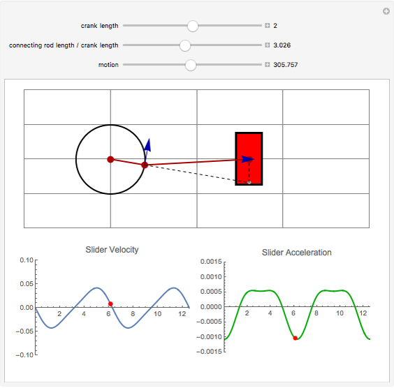
A slider-crank linkage is a four-link mechanism with three revolute joints and one prismatic, or sliding, joint. The rotation of the crank drives the linear movement the slider, or the expansion of gases against a sliding piston in a cylinder can drive the rotation of the crank.
Which mechanism is crank fixed?
3) Rotary Engine : while the crank (link 2) is fixed. In this mechanism, when the connecting rod (link 4) rotates, the piston (link 3) reciprocates inside the cylinders forming link 1.
How does double crank mechanism work?
Double Crank Mechanism converts a reciprocating motion to a rotational motion and vice versa. Interesting for this mechanism is that it has three moments of standstill. This project aims at carrying structural analysis on the mechanism with two different loading configurations.
What is a crank in technology?
A crank is an arm attached at a right angle to a rotating shaft by which circular motion is imparted to or received from the shaft. When combined with a connecting rod, it can be used to convert circular motion into reciprocating motion, or vice versa.
What is piston crank mechanism?
This mechanism has four parts: The crank is attached to a motor that rotates it. The rod is attached to the crank and the piston at joints that are free to rotate. The guide is fixed in place; its purpose is to make the piston move in a line. The piston is free to move up and down in a line but cannot rotate.
Where are crank mechanisms used?
Internal combustion engines are a common example of this mechanism, where combustion in a cylinder creates pressure which drives a piston. The piston's linear motion is converted into rotational motion at the crank through a mutual link, referred to as the connecting rod.
What is crank and slotted lever mechanism?
The crank and slotted lever quick return mechanism converts the rotary motion into reciprocating motion. It is the inversion of single slider crank chain. This mechanism consists of two strokes cutting stroke (forward stroke) and idle stroke (return stroke).
Where are crankshafts used examples?
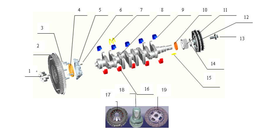
A crankshaft is a mechanical part that is used to convert the reciprocating motion of a piston into rotational motion....Examples of CrankshaftDiesel Engines. ... Electric Generators. ... Internal Combustion Engines. ... Drive Camshafts. ... Transmit Power to Parts of an Engine. ... Motorcycles.
What is the purpose of a reciprocating crank?
Almost all reciprocating engines use cranks (with connecting rods) to transform the back-and-forth motion of the pistons into rotary motion. The cranks are incorporated into a crankshaft .
What is a crank on a sailboat?
A crank is an arm attached at a right angle to a rotating shaft by which circular motion is imparted to or received from the shaft. When combined with a connecting rod, it can be used to convert circular motion into reciprocating motion, or vice versa.
What is the rod on a bicycle crank?
Attached to the end of the crank by a pivot is a rod, usually called a connecting rod (conrod). The term often refers to a human-powered crank which is used to manually turn an axle, as in a bicycle crankset or a brace and bit drill. In this case a person's arm or leg serves as the connecting rod, applying reciprocating force to the crank.
What is a connecting rod?
When combined with a connecting rod, it can be used to convert circular motion into reciprocating motion, or vice versa. The arm may be a bent portion of the shaft, or a separate arm or disk attached to it. Attached to the end of the crank by a pivot is a rod, usually called a connecting rod (conrod). The term often refers to a human-powered crank ...
When did cranks become common?
The crank became common in Europe by the early 15th century , often seen in the works of those such as the German military engineer Konrad Kyeser. Devices depicted in Kyeser's Bellifortis include cranked windlasses (instead of spoke-wheels) for spanning siege crossbows, cranked chain of buckets for water-lifting and cranks fitted to a wheel of bells. Kyeser also equipped the Archimedes screws for water-raising with a crank handle, an innovation which subsequently replaced the ancient practice of working the pipe by treading. The earliest evidence for the fitting of a well-hoist with cranks is found in a miniature of c. 1425 in the German Hausbuch of the Mendel Foundation.
What is a hand crank for a winch on a sailboat?
Hand crank for a winch on a sailboat - commonly referred to as a winch handle .
Where was the first crank sawmill?
The earliest evidence for the crank combined with a connecting rod in a machine appears in the Roman Hierapolis sawmill in Asia Minor from the 3rd century AD and two Roman stone sawmills at Gerasa, Roman Syria, and Ephesus, Asia Minor (both 6th century AD). On the pediment of the Hierapolis mill, a waterwheel fed by a mill race is shown powering via a gear train two frame saws which cut rectangular blocks by the way of some kind of connecting rods and, through mechanical necessity, cranks. The accompanying inscription is in Greek.
What is a crank in an engine?
Most engines use cranks to do this. A crank is simply an off-center connection that provides energy to (or takes energy from) a rotating wheel. As the crank pushes back and forth, the wheel rotates (or vice-versa).
Why are bicycle pedals called cranks?
Photo: Bicycle pedals would be better referred to as "bicycle cranks," because it's the cranks attached to the pedals that do the work!
How do cams work?
Cams generally do the opposite job to cranks: they turn rotary motion into reciprocating motion. Whatever you need to move up and down (or back and forth) rests on top of an oval wheel, sometimes mounted off-center (the cam). As the cam rotates, the object it supports rises up and down. In this example, you can see the blue box rises and falls as the green cam turns round and round. But most of the time the box just sits there, motionless, with the cam slowly spinning beneath it. If you look closely at the way I've drawn the cam, you can see the secret of how it works. Three "quarters" of it is like a circle, so anything resting on it for three quarters of the time will neither rise nor fall, but stay motionless. The other quarter stretches out into an ellipse shape and that's the part that lifts and lowers every time it reaches the top.
How do steam engines work?
An engine like this typically makes power with a single piston moving in and out of a single cylinder. If you need it drive a wheel, you can attach the piston to a beam. As the piston moves up and down, the beam rocks back and forth, pulling on a crankshaft and connecting rod that turn the wheel.
What is the book Making Wooden Mechanical Models?
Making Wooden Mechanical Models: 15 Designs with Visible Wheels, Cranks, Pistons, Cogs, and Cams by Alan and Gill Bridgewater, F+M Media, 2011. There's no better way to understand cams and crans than building your own little machines that use them. This book is published by Popular Woodworking magazine and includes designs for simple engines, pumps, locks, governors (speed regulators), and oscillators.
What happens when a cam rotates?
As the cam rotates, the object it supports rises up and down. In this example, you can see the blue box rises and falls as the green cam turns round and round. But most of the time the box just sits there, motionless, with the cam slowly spinning beneath it.
Why can't you increase the speed and force simultaneously?
Why can't you increase the speed and the force simultaneously? Because of a basic law of physics called the conservation of energy. Suppose you're cranking the clockwork radio. You apply a certain force to the handle to move it a certain distance in one second. That takes a certain amount of energy, which your body supplies. Now the law of conservation of energy tells us nothing can magically create energy out of thin air: the energy you supply to the outside (the crank handle) must be the same (or a bit less) than the energy received at the inside (the center of the crank where the clockwork mechanism is located). We know we're getting more force at the center of the crank than at the outside; we also know that the inside of the crank turns more slowly (less distance each second) than the outside. So the greater force is compensated by that force moving a shorter distance each second. Every second, the energy supplied to the inner, clockwork mechanism at the center (the larger force times the shorter distance) is virtually the same as the energy we put in at the outer part of the crank (the smaller force times the longer distance).
Overview
A crank is an arm attached at a right angle to a rotating shaft by which circular motion is imparted to or received from the shaft. When combined with a connecting rod, it can be used to convert circular motion into reciprocating motion, or vice versa. The arm may be a bent portion of the shaft, or a separate arm or disk attached to it. Attached to the end of the crank by a pivot is a rod, …
Examples
Familiar examples include:
• Spinning Wheel
• Mechanical pencil sharpener
• Fishing reel and other reels for cables, wires, ropes, etc.
History
It was thought that evidence of the earliest true crank handle was found in a Han era glazed-earthenware tomb model of an agricultural winnowing fan dated no later than 200 AD, but since then a series of similar pottery models with crank operated winnowing fans were unearthed, with one of them dating back to the Western Han dynasty (202 BC - 9 AD). Historian Lynn White stated that the …
Crank axle
A crank axle is a crankshaft which also serves the purpose of an axle. It is used on steam locomotives with inside cylinders.
See also
• Beam engine – Early configuration of the steam engine utilising a rocking beam to connect major components.
• Crankshaft – Mechanism for converting reciprocating motion to rotation
• Piston motion equations
Bibliography
• Curtis, Robert I. (2008). "Food Processing and Preparation". In Oleson, John Peter (ed.). The Oxford Handbook of Engineering and Technology in the Classical World. Oxford: Oxford University Press. ISBN 978-0-19-518731-1.
• Frankel, Rafael (2003), "The Olynthus Mill, Its Origin, and Diffusion: Typology and Distribution", American Journal of Archaeology, 107 (1): 1–21, doi:10.3764/aja.107.1.1
External links
• Crank highlight: Hypervideo of construction and operation of a four cylinder internal combustion engine courtesy of Ford Motor Company
• Kinematic Models for Design Digital Library (KMODDL) - Movies and photos of hundreds of working mechanical-systems models at Cornell University. Also includes an e-book library of classic texts on mechanical design and engineering.