There are three basic types of wiring diagrams:
- Wiring: Depicts electrical devices as drawings or pictures connected by lines representing wires. Wiring diagrams show specific electrical connections.
- Pictorial: Shows how components are related to others on the same circuit, but contains less detailed information about electrical connections.
- Schematic: Represents the flow of electricity through a circuit and its components. ...
How to make electrical wiring diagrams?
Tips for Drawing a House Wiring Diagram Efficiently
- Make sure to draw enough outlets for the bedroom bathroom and kitchen plans. You need to keep at least three in each case.
- Clearly picture where you want your furniture, and position the outlets accordingly for easy access.
- Outdoor lighting is also important and so try to keep the outlets nearby doors.
- Decide wisely how the wiring will be laid out. ...
How to read wiring diagrams?
A car wiring diagram is a map. To read it, identify the circuit in question and starting at its power source, follow it to the ground. Use the legend to understand what each symbol on the circuit means.
What does wiring diagram mean?
What is a Wiring Diagram? A wiring diagram is a simple visual representation of the physical connections and physical layout of an electrical system or circuit. It shows how the electrical wires are interconnected and can also show where fixtures and components may be connected to the system.
What are the basics of electrical wiring?
It boils down to three basic components:
- Service Entry. This refers to the point in your home where your electrical service goes from the main grid into your home. ...
- Panel Board. Your panel board is your control center when it comes to electrical wiring. ...
- Branch Circuits. This refers to the isolated areas of areas of your home where your panel board directs electrical currents. ...
What do wiring diagrams give information about?
It shows the components of the circuit as simplified shapes, and how to make the connections between the devices. A wiring diagram usually gives more information about the relative position and arrangement of devices and terminals on the devices.
What do electrical diagrams consist of?
Electrical diagrams are drawings which are used to represent electrical circuits, these circuits are represented by using lines, symbols, and number combinations. Electrical diagrams show the wiring between components and the relative position of the components.
Where is a wiring diagram used?
Wiring diagrams are mainly used when trying to show the connection system in a circuit. It is majorly used by building planners, architects, and electricians to present the wiring connections in a building, a room, or even a simple device.
What is a wiring diagram called?
Schematic Diagrams The schematic diagram (Figure 6.2. 1), often called a ladder diagram, is intended to be the simplest form of an electrical circuit. This diagram shows the circuit components on horizontal lines without regard to their physical location.
What are the 3 types of wiring diagrams?
Types of Electrical Diagrams or Schematics There are three ways to show electrical circuits. They are wiring, schematic, and pictorial diagrams.
How do you read a wiring diagram?
3:0910:54How to Read Electrical Diagrams | Control Panel Wiring DiagramYouTubeStart of suggested clipEnd of suggested clipFirst of all there is a rule of thumb in standard wiring diagrams that you should read the diagramMoreFirst of all there is a rule of thumb in standard wiring diagrams that you should read the diagram from left to right. And from top down exactly like reading a book.
Why is wiring diagram important?
A wiring diagram usually gives information about the relative position and arrangement of devices and terminals on the devices, to help in building or servicing the device.
What is the main reason for using a circuit diagram?
Circuit diagrams are used for the design (circuit design), construction (such as PCB layout), and maintenance of electrical and electronic equipment.
What is the difference between circuit diagram and wiring diagram?
Wiring Diagram shows the actual practical connection between electrical appliances, components. Circuit Diagram just shows the simple connection between components it does not shows the practical connection.
How do you make a wiring diagram?
How to Draw Electrical DiagramsStart with a collection of electrical symbols appropriate for your diagram.Draw circuits represented by lines.Drag and drop symbols to the circuits and connect them.Use line hops if any lines need to cross.
What are the 4 types of diagram?
There are four main organizational chart types: vertical, horizontal, matrix and creative.
How do you draw an electrical diagram?
2:184:59How to Draw Circuit and Electrical Diagrams with SmartDraw - YouTubeYouTubeStart of suggested clipEnd of suggested clipPoints. And to change the size and shape of your line hops. Select show dimensions to show theMorePoints. And to change the size and shape of your line hops. Select show dimensions to show the length of your lines. Or the area of your shapes.
What are the three types of electrical diagrams used in the HVAC industry?
There are three basic types of circuit schematics used in HVAC today. They are the Line Diagram, the Ladder Diagram, and the Installation Diagram. You can think of these circuit schematics as road maps.
What are the 4 types of circuit?
The main types of electric circuits are Close Circuit, Open Circuit, Short Circuit, Series Circuit, and Parallel Circuit. Electric circuit provides the conductive path for the flow of electric charge or electric current.
What Is A Wiring Diagram?
A wiring diagram is a simple visual representation of the physical connections and physical layout of an electrical system or circuit. It shows how...
When and How to Use A Wiring Diagram
Use wiring diagrams to assist in building or manufacturing the circuit or electronic device. They are also useful for making repairs.DIY enthusiast...
How to Draw A Circuit Diagram
SmartDraw comes with pre-made wiring diagram templates. Customize hundreds of electrical symbols and quickly drop them into your wiring diagram. Sp...
How Is A Wiring Diagram Different from A Schematic?
A schematic shows the plan and function for an electrical circuit, but is not concerned with the physical layout of the wires. Wiring diagrams show...
How Is A Wiring Diagram Different from A Pictorial Diagram?
Unlike a pictorial diagram, a wiring diagram uses abstract or simplified shapes and lines to show components. Pictorial diagrams are often photos w...
Standard Wiring Diagram Symbols
If a line touching another line has a black dot, it means the lines are connected. When unconnected lines are shown crossing, you'll see a line hop...
What are the symbols on a wiring diagram?
For example, a surface ceiling light is shown by one symbol, a recessed ceiling light has a different symbol, and a surface fluorescent light has another symbol. Each type of switch has a different symbol and so do the various outlets. There are symbols that show the location of smoke detectors, the doorbell chime, and thermostat. On large projects symbols may be numbered to show, for example, the panel board and circuit to which the device connects, and also to identify which of several types of fixture are to be installed at that location.
What is an architectural wiring diagram?
Architectural wiring diagrams show the approximate locations and interconnections of receptacles, lighting, and permanent electrical services in a building. Interconnecting wire routes may be shown approximately, where particular receptacles or fixtures must be on a common circuit.
What is the difference between a schematic diagram and a wiring diagram?
This is unlike a schematic diagram, where the arrangement of the components' interconnections on the diagram usually does not correspond to the components' physical locations in the finished device. A pictorial diagram would show more detail of the physical appearance, whereas a wiring diagram uses a more symbolic notation to emphasize interconnections over physical appearance.
What is a wiring diagram for an electric guitar?
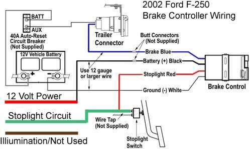
A wiring diagram for parts of an electric guitar, showing semi-pictorial representation of devices arranged in roughly the same locations they would have in the guitar. An automotive wiring diagram, showing useful information such as crimp connection locations and wire colors.
Why do we need wiring diagrams?
A wiring diagram is often used to troubleshoot problems and to make sure that all the connections have been made and that everything is present.
Legend Page
The first thing that you have to care about is the “Legend” page, this page is attached with every wiring diagram and it describes every symbol in the whole wiring, as we can see in Fig (2).
Direction of the Drawing
The common direction to draw a wiring diagram is from UP to DOWN and from LEFT to RIGHT.
Connecting the wiring together
You have to know that all of the wiring papers are attached together to build a single panel.
Marshalling Terminals
As we can see in the previous figures the panel is connected with the outside field via Marshalling terminals.
Sizing of the cables and wiring data
You might see also in some wiring diagrams (not all of them) the sizing of power cables as you could see in figure (11) the size of the cable that is connected to the motor is 6mm 2.
About the author
I am Hussein Junior Mechatronics Engineer, I have specialized in Automation Industry and I have made many projects that are related to PLC Programming - Instrumentation Installation - Networking - Circuit Design - Motion Control.
What do the lines in a circuit diagram represent?
While the horizontal and vertical lines of a schematic show the circuit’s flow, lines in a wiring diagram instead represent the physical wiring of the circuit.
Why are schematic diagrams different from other electrical wiring diagrams?
1. Schematic Diagrams. Schematic electrical wiring diagrams are different from other electrical wiring diagrams because they show the flow through the circuit rather than the physical layout of any equipment.
What is schematics used for?
Schematics can be used for general information about the flow of the current as well as troubleshooting a circuit since they show wiring and components using specific symbols that actually show the function of equipment within the circuit; however, these symbols don’t look like the equipment itself.
What is a wiring diagram?
Wiring Diagram. A wiring diagram is the most common form of the electrical wiring diagram. Unlike a schematic, it’s concerned with the connections between the different parts of a circuit or parts of an entire electrical system. Wiring and equipment on the wiring diagram are carefully laid out to show the approximate location ...
What is system flow diagram?
The system flow is shown by a series of horizontal and vertical lines, much like a normal electrical wiring diagram. However, in this case, the lines show the flow of the system rather than the actual physical placement of the wires within the system. It’s an electrical wiring diagram that’s aimed more at designers and technicians who work with the theory of the circuit. Schematics will not be ideal for anyone who plans on working on the circuit as it is in the house.
What is the purpose of electrical wiring diagrams?
There are several different types of electrical wiring diagrams. They all do essentially the same thing, which is to show you how circuits are wired. However, the variation in these diagrams shows how circuits are mapped out in different ways to accomplish different ends. The type of electrical wiring diagram you use depends on what you want to achieve with it.
What is the purpose of articles being reviewed?
To ensure our content is always up-to-date with current information, best practices, and professional advice, articles are routinely reviewed by industry experts with years of hands-on experience.
What is a House Wiring Diagram?
A wiring diagram is a pictorial representation of an electric circuit, where the elements of the loop and the signal connections between devices and the power source are shown in the conventional methods as simplified shapes. A house wiring diagram is thus, a wiring diagram of a house.
How to draw a House Wiring Diagram with EdrawMax?
It is the place where we go through the steps you need to take to create a house wiring diagram with EdrawMax. However, before we start, there are a few things you need to know about the interface.
How many watts does a bathroom switch have?
Let us consider the following bathroom wiring diagram. Here we see three switches in the central switchboard. Switch one connects the four 60 Watt bulbs at the left side above the washing sink. Switch two connects to the central ceiling fan and two 50 Watt lights connected by Switch three.
Why is wiring diagram important?
A useful house wiring diagram can show electricians where the points of damage lie in the whole network. It can help them to avoid sharp places, open live wires, and many other such scenarios.
What happens if an electrician doesn't use a wiring diagram?
Say your electrician does not use a house wiring diagram, this can lead to severe inefficiency. There can be two possible scenarios: One, without an exact amount, your electrician may end up using more wiring which can lead to wastage of the extra installation and by means wastage of money;
What is a square pattern on a basement wiring diagram?
As we see in the following Basement Wiring Diagram, the square patterns are switches while the circular or rectangular patterns are light fixtures. A simple wiring diagram shows the connections in series and parallel for the various electrical appliances such as bulbs. Different sections colored in different colors here do not represent the color coding of wires.
What is electrical design?
It is the visual representation or design of the entire electrical wiring system or circuitry of a house (or a room) that helps in creating the system so as to distribute energy that can be used to power the various equipments and appliances around the house through proper installation and operation of the different elements included in the design such as electrical outlets, meter base, switches and breakers and more.
What is a wiring diagram?
The wiring diagram shows the different components of the circuit as simplified and standard pictograms, and the power and signal connections (buses) between the devices. Arrangement of the components and interconnections on the wiring diagram does not usually correspond to their physical locations in the finished device.
Can you find wiring diagrams in a Haynes manual?
If you only need wiring diagrams for your own car or truck, the best option might be a manual from Chilton or Haynes, or the factory manual. All Chilton Total Car Care and Haynes Repair Manuals include electrical wiring diagrams. Wiring diagrams can also be found in factory service manuals or separate factory wiring diagrams manuals. Factory publications vary, sometimes there is a separate manual for electrical wiring diagrams, sometimes they are included in the full service manual. Use the links above to start searching our products, and please contact us with any questions.