What is Ch_pd pin in esp8266?
The pin on the top right side is the RX pin and the pin on the lower left is TX. These are the pins for comunication. The middle pins on the bottom are CH_PD(chip power-down) and RST(reset). The main thing to remember is, that this device works with 3.3V;even the RX and TX pins.
What is node MCU pins?
NodeMCU has four pins available for SPI communication. UART Pins. TXD0, RXD0, TXD2, RXD2. NodeMCU has two UART interfaces, UART0 (RXD0 & TXD0) and UART1 (RXD1 & TXD1). UART1 is used to upload the firmware/program.
What is the use of TX pin?
The Tx pin is used to transmit data. When two devices are connected using a UART, the Rx pin of one device is connected to the Tx pin of the second device.
CAN NodeMCU run on 12v?
Possible. But not a good idea (if you power anything but the NodeMCU itself your regulator will overheat - that includes the blue built-in LED). I wasn't ever able to get it working reliably at 12v... I would not try to run something that pulls as much current as an ESP32 can from 12v via a linear regulator.
What does a NodeMCU do?
NodeMCU is an open source platform based on ESP8266 which can connect objects and let data transfer using the Wi-Fi protocol. In addition, by providing some of the most important features of microcontrollers such as GPIO, PWM, ADC, and etc, it can solve many of the project's needs alone.
How many pins are in NodeMCU?
17 GPIO pinsGPIO Pins NodeMCU/ESP8266 has 17 GPIO pins which can be assigned to functions such as I2C, I2S, UART, PWM, IR Remote Control, LED Light and Button programmatically. Each digital enabled GPIO can be configured to internal pull-up or pull-down, or set to high impedance.
Does NodeMCU have analog pins?
However, the biggest disadvantage of the NodeMCU board is that it has only one Analog pin. In other words, it only can measure from 1 sensor. If we have projects that require more than one sensor, we will need to find another micro-controller with more Analog Pins such as Arduino UNO or MEGA.
What can we do with NodeMCU?
By using a NodeMCU coupled with a GPS/GSM shield, it can communicate the weather even in remote areas and automatically upload the data to Google Sheets for easy viewing.
What are the pins on an ESP8266?
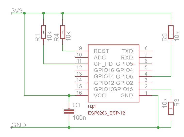
The ESP8266-01 is the smallest ESP8266 module and only has 8 pins. Of these VCC, GND, RST (reset) and CH_PD (chip select) are not I/O pins but are needed the operation of the module. This leaves GPIO0, GPIO2, TX and RX available as possible I/O pins, but even these have pre-assigned functions. The GPIO0 and GPIO2 determine what mode the module starts up in and the TX/RX pins are used to program the module and for Serial I/O, commonly used for debugging. GPIO0 and GPIO2 need to have pull-up resistors connected to ensure the module starts up correctly.
How to get extra inputs into ESP8266-01?
The best trick to get extra inputs into the ESP8266-01 is to use an I2C interface.
What is ESP8266-01?
ESP8266-01 is a very low cost WiFi enabled chip. But it has very limited I/O. At first glance, once you configure it for programming all the pins are used.
What are pull up resistors?
The pull-up resistors, R1 and R3, provide the necessary High for these two pins, but you have to ensure that any extra circuitry attached to GPIO0 and GPIO2 cannot not pull pins low. The optically isolated relay is connected between +3.3V and GPIO0. This keeps GPIO0 high on start up but allows GPIO0 to be made an output, after startup, and ground the relay input to operate the relay. It does not matter if the momentary push button is operated while the module is initializing, as that just connects GPIO0 to GPIO2 and connect both of these to their pullup resistors.
What is GPIO0 in WiFi?
Here GPIO0 is used as an output to drive the relay and GPIO0/GPIO2 is used as an input to read the momentary push button which is used as a manual override to turn the relay on and off, in addition to the remote control over the WiFi connection. The momentary push button is also used to enable the config mode if it is press when power is applied.
Why is GPIO1 used as a data line?
A few things to note: GPIO1 (TX) is used as the Data line, because you will always get some debug output on GPIO1 on power up. There is no way to suppress this output, but the Clock line (RX) will be held high so none of this data will be clocked to the slaves.
Is the ESP8266 3.3V?
The ESP8266 is 3.3 V device so preferably use 3.3V I2C slaves. Many, but not all, I2C devices are are 3.3V these days. “In general, in a system where one device is at a higher voltage than another, it may be possible to connect the two devices via I2C without any level shifting circuitry in between them.