What is the line joining the vertical and horizontal planes?
As you can see in the isometric drawing, the line joining both, vertical and horizontal planes, is the x-y line about which they are pivoted or opened from the normal 90-degree angle to each other.
What is a plan drawing in architecture?
Plan drawings are a specific type of drawing architects use to illustrate a building or portion of a building. A plan is drawn from a horizontal plane looking down from above. This is as if you sliced through a space horizontally and stood over looking down on it.
What is the difference between plan section section and elevation drawing?
Plan, Section, and Elevation are different types of drawings used by architects to graphically represent a building design and construction. A plan drawing is a drawing on a horizontal plane showing a view from above. An Elevation drawing is drawn on a vertical plane showing a vertical depiction.
What are the basic components of engineering drawing?
Basic Components of an Engineering Drawing. 1 Isometric View. Isometric drawings show parts as three-dimensional. All the vertical lines stay vertical (compared to front view) and otherwise ... 2 Orthographic View. 3 Flat Pattern. 4 Section View. 5 Cutout View. More items

What is horizontal plane and vertical plane in engineering drawing?
1 Reference planes Principal planes - horizontal plane and vertical plane –are the main reference planes used in orthographic projections. Profile plane, auxiliary vertical plane, and auxiliary inclined plane are also used as reference planes when two views of the object are not sufficient.
What is vertical plane in engineering drawing?
Definition of vertical plane 1 : a plane that passes through a vertical line. 2 : a plane of perspective passing through the point of sight and perpendicular to the ground plane and to the picture.
What is horizontal plane?
aka transverse plane, a horizontal plane divides the brain into a superior and inferior portion. It is created by slicing the brain perpendicular to the long axis of the body, and thus parallel to the floor in a person that is upright.
What is horizontal plane example?
The floor or ceiling is a perfect example of a horizontal plane or horizontal surface. Perpendicular to the floor, the wall is a great example of a vertical plane.
What is vertical and horizontal?
Anything parallel to the horizon is called horizontal. As vertical is the opposite of horizontal, anything that makes a 90-degree angle (right angle) with the horizontal or the horizon is called vertical. So, the horizontal line is one that runs across from left to right.
What is the vertical plane called?
vertical plane one perpendicular to a horizontal plane, such as a sagittal plane, median plane, or frontal plane.
Which plane is horizontal plane only?
The transverse planeThe transverse plane is the only horizontal plane, and it divides the body into top (superior) and bottom (inferior) sections.
Is a horizontal plane flat?
an imaginary flat surface that divides the body or brain into upper and lower parts. Also called transverse plane.
What is the equation of a horizontal plane?
A horizontal plane is of the form z=c. The fact that z doesn't appear in the equation 2x−y=3 means that the intersection of this plane with a plane of the form z=c always has the same equation (viewed as an equation in the plane z=c), namely 2x−y=3.
What is horizontal line?
A horizontal line is a straight line that goes from left to right or right to left. In coordinate geometry, a line is said to be horizontal if two points on the line have the same Y- coordinate points. It comes from the term “horizon”. It means that the horizontal lines are always parallel to the horizon or the x-axis.
Why is it called vertical?
The word vertical is derived from the late Latin verticalis, which is from the same root as vertex, meaning 'highest point' or more literally the 'turning point' such as in a whirlpool. Girard Desargues defined the vertical to be perpendicular to the horizon in his 1636 book Perspective.
What is profile plane?
Answer: A third plane perpendicular to both coordinate planes, and hence to the ground line, is called a profile plane. This plane is vertical in position, and may be used as a plane of projection. Projections of a Line on Horizontal, Vertical, and Profile Planes.
What is the difference between horizontal plane and vertical plane?
In astronomy, geography, and related sciences and contexts, a direction or plane passing by a given point is said to be vertical if it contains the local gravity direction at that point. Conversely, a direction or plane is said to be horizontal if it is perpendicular to the vertical direction.
What is vertical plane of cleavage?
Vertical plane of cleavage: When a furrow passes in any direction (does not pass through the median axis) from the animal pole towards the opposite pole.
What are different types of planes of projection?
Projection of planes: When the given plane is perpendicular to one reference planePlane Perpendicular to VP and Parallel to HP. ... Plane Perpendicular to VP and In HP. ... Plane Perpendicular to HP and Parallel to VP. ... Plane Perpendicular to HP and in VP. ... Plane Perpendicular to VP and Perpendicular to HP.More items...
What is another name for the transverse plane?
axial planeA transverse plane, also known as an axial plane or cross-section, divides the body into cranial and caudal (head and tail) portions.
What is engineering drawing?
An engineering drawing is a subcategory of technical drawings. The purpose is to convey all the information necessary for manufacturing a product or a part. Engineering drawings use standardised language and symbols. This makes understanding the drawings simple with little to no personal interpretation possibilities.
What does it mean when a line is vertical and parallel?
The lines that are vertical and parallel are in their true length. Which means you can use a ruler and the scaling of the drawing to easily measure the length straight from a paper drawing, for example. The same does not apply to angled lines. Left – perspective; right – isometric.
What is orthographic view?
This is the bread and butter of an engineering drawing. An orthographic view or orthographic projection is a way of representing a 3D object in 2 dimensions.
What is hidden line?
Hidden lines can show something that would not be otherwise visible on the drawings. For example, hidden lines may show the length of an internal step in a turned part without using a section or a cutout view (we explain both later). Centre lines are used to show hole and the symmetric properties of parts.
What does the line thickness mean in drawing?
This represents the physical boundaries of an object. Put simply, these lines are for drawing the objects. The line thickness varies – the outer contour uses thicker lines and inner lines are thinner. Hidden lines can show something that would not be otherwise visible on the drawings.
What are the different types of lines in engineering?
The different options make it possible to show both visible and hidden edges of a part, centre lines, etc. The most common is a continuous line, also known as a drawing line . This represents the physical boundaries of an object.
Can you use sheet metal in CAD?
Just be aware that you are using the sheet metal environment when making sheet metal parts in CAD. There you have the option to “generate a flat pattern” which you can easily add to the main drawing. If you are using the standard part environment, the same option is not available.
What is a plan drawing?
Plan drawings are specific drawings architects use to illustrate a building or portion of a building. A plan is drawn from a horizontal plane looking down from above. This is as if you sliced through a space horizontally and stood over looking down on it. Plans are a common design drawing and technical architectural or engineering convention for graphic representation of architecture. With the exception of plan perspectives, plan drawings are orthographic projections. This means they are not drawn in perspective and there is no foreshortening.
What is detail in architectural drawings?
Details in architectural drawings are large scale drawings that typically show how something is built. Details identify all the materials and connections for construction. Details are normally 3/4″ = 1′-0″ or larger. Plan details are drawn in a plan view at a large scale to show the construction.
What is plan perspective?
A plan perspective is a drawing of a plan but shown in perspective. This is more of a design drawing meant to show what the space is going to look like and less how the space will be built.
How high is a plan cut?
The plan is typically cut at a height of about 4 feet , but the architect drawing the plan may cut it at a different height. This means that you have an imaginary plane cutting through the building at an elevation of 4 feet above the floor. Therefore, you see in the cut anything that the plane passes through.
What is section in architecture?
Sections are a common design drawing and technical architectural or engineering convention for graphic representation of architecture.
Which surface needs its own projection plane to show the features correctly?
parallel to the object surface. Therefore, any surface that is not in line with the three major axis needs its own projection plane to show the features correctly.
What is engineering graphic design?
Engineering graphics is an effective way of communicating technical ideas and it is an essential tool in engineering design where most of the design process is graphically based. Engineering graphics is used in the design process for visualization, communication, and documentation. Graphics is a visual communications language that include images, text, and numeric information. Graphics communications using engineering drawings and models is a clear and precise language with definite rules that must be mastered in order to be successful in engineering design. Graphics communications are used in every phase of engineering design starting from concept illustration all the way to the manufacturing phase. An engineering (or technical) drawingis a graphical representation of a part, assembly, system, or structure and it can be produced using freehand, mechanical tools, or computer methods. Working drawingsare the set of technical drawings used during the manufacturing phase of a product. They contain all the information needed to manufacture and assemble a product.
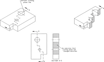
How to make a half section?
A half section is made by passing two perpendicular imaginary cutting planes halfway through an object such that one quarter of the object is removed. Hidden lines are omitted on both halves of the section view. External features of the part are drawn on the unsectioned half of the view. A center line, not an object line, is used to separate the sectioned half from the unsectioned half of the view. Half section views are most often used on parts that are symmetrical, such as cylinders.
What is standard layout of drawing sheets?
Standard layouts of drawing sheets are specified by the various standards organizations. The figure shows the layout of a typical sheet, showing the drawing frame, a typical title block, parts list (bill of materials) and revision table.
Why are different lines important in drawings?
The use of different line styles and widths is important in technical drawings as they are used to indicate details and features of the drawing. Line styles make drawings easier to read where for example, solid lines used to show the object will stand out from dashed lines used to show hidden features. The four main types of lines used in drawings are listed in the table:
Where is the title block on a CAD drawing?
Title Block, The title block is normally placed in the bottom right of the drawing frame , and it should contain the following information: the name of the company or organization the title of the drawing the drawing number, which is generally a unique filing identifier the scale the drawing size the angle of projection used, either first or third, generally shown symbolically the signature or initials of the draftsman, checker, approving officer, and issuing officer, with the respective dates the material of the part the revision number the sheet number for multi-sheet drawings other information as required (tolerances, surface finish, etc.) In addition to the information above, for drawings produced using CAD software, it is highly recommended to have the following information in the title block: the name of the CAD software used and its version the name of the drawing file the name of the source part or assembly file the units of the dimensions (if the drawing is mistakenly printed on a different paper size, the scale becomes meaningless)
Which projection scheme is used to position views relative to each other?
The views are positioned relative to each other according to either of two schemes: first-angle or third-angle projection.