
What is an l293d Motor Driver module?
L293D Motor Driver Module L293D is a basic motor driver integrated chip (IC) that enables us to drive a DC motor in either direction and also control the speed of the motor. The L293D is a 16 pin IC, with 8 pins on each side, allowing us to control the motor. It means that we can use a single L293D to run up to two DC motors.
What is the l293d used for?
The L293D is a 16-pin Motor Driver IC which can control a set of two DC motors simultaneously in any direction. The L293D is designed to provide bidirectional drive currents of up to 600 mA (per channel) at voltages from 4.5 V to 36 V (at pin 8!). You can use it to control small dc motors - toy motors.
How many motors can a l293d Shield control?
The motor driver shield has two L293D motor driver IC. So, the L293d shield able to control four DC motors or one stepper motor. The 74HC595 is a shift resistor IC. This IC has an 8-bit shift register and an 8-bit D-type latch with three state parallel outputs.
What is the power output of the l293d IC?
The L293D IC has a supply range of 4.5V to 36V and is capable of 1.2A peak output current per channel, so it works very well with most of our motors. The IC also includes built-in kick-back diodes to prevent damage when the motor is de-energized. For more details, please refer below datasheet.
What is a L293D IC?
How to use L293D?
Why we need a Motor Driver?
Who invented the DC motor?
Can L293D be used without limitations?
How does L293D IC work?
L293D IC is a typical Motor Driver IC which allows the DC motor to drive on any direction. This IC consists of 16-pins which are used to control a set of two DC motors instantaneously in any direction. It means, by using a L293D IC we can control two DC motors. As well, this IC can drive small and quiet big motors.
How do you use a L293D motor driver IC?
Place the L293D in the center of the breadboard, with half of the pins on either side of the breadboard. Connect 5V to Enable 1 , Vss , and Vs on the L293D. Connect digital output pins (we're using 6 and 7) to input 1 and input 2 on the L293D. Connect your Arduino's GND to both GND pins on the same side of the L293D.
What is a L293D motor driver chip?
The L293D is a popular 16-Pin Motor Driver IC. As the name suggests it is mainly used to drive motors. A single L293D IC is capable of running two DC motors at the same time; also the direction of these two motors can be controlled independently.
What is the use of motor driver IC?
Motor Driver ICs are commonly used in robotics to drive DC motors from microcontrollers. They are an essential component in controlling motion in autonomous robots, and so are widely used in automation. They are also found in more common environments, such as office appliances and in automotive electronics.
Why L293D IC is used?
The L293D is designed to provide bidirectional drive currents of up to 600-mA at voltages from 4.5 V to 36 V. Both devices are designed to drive inductive loads such as relays, solenoids, DC and bipolar stepping motors, as well as other high-current/high-voltage loads in positive-supply applications.
What does L293D stand for?
L293D is a dual H-bridge motor driver integrated circuit (IC). Motor drivers act as current amplifiers since they take a low-current control signal and provide a higher-current signal. This higher current signal is used to drive the motors. L293D contains two inbuilt H-bridge driver circuits.
How does L293D control speed?
To control the speed of the motor : The speed is set by using an analogWrite to the enable pin. Speed of the motor can be changed by changing the value in "analogWrite", The motor spins at a maximum speed if the value in analogWrite is set as 255.
Is L293D a microcontroller?
L293D is a dual H-bridge, high current motor driver Integrated Circuit. It acts as a current amplifier as it takes a low current input signal from the microcontroller and provides high current output to the motor. It supports a peak voltage of 36 V and a peak current of 600mA per channel.
Which IC is used in L293D motor shield?
L293D shield is a driver board based on L293 IC, which can drive 4 DC motors and 2 stepper or Servo motors at the same time. Each channel of this module has the maximum current of 1.2A and doesn't work if the voltage is more than 25v or less than 4.5v.
What are the benefits of motor drivers?
Consider these 10 benefits of operating motors with adjustable speed drives:Controlled starting current. ... Reduced power line disturbances. ... Lower power demand on start. ... Controlled acceleration. ... Adjustable operating speed. ... Adjustable torque limit. ... Controlled stopping. ... Energy savings.More items...•
What is IC of motor?
An internal combustion engine (ICE or IC engine) is a heat engine in which the combustion of a fuel occurs with an oxidizer (usually air) in a combustion chamber that is an integral part of the working fluid flow circuit.
How many motors can be controlled using L293D?
two DC motorsThe L293D is a 16-pin Motor Driver IC which can control up to two DC motors simultaneously, in any direction.
Where can I use L293D IC?
The L293D is a 16-pin Motor Driver IC which can control a set of two DC motors simultaneously in any direction. The L293D is designed to provide bidirectional drive currents of up to 600 mA (per channel) at voltages from 4.5 V to 36 V (at pin 8!). You can use it to control small dc motors - toy motors.
How do you use a motor driver?
To drive a motor to a direction, say, clockwise, the pin Input 1 must be high while the pin Input 2 must be low. To drive the motor counter clockwise, the pin Input 1 is low while the pin Input 2 is high. The diagram above shows an example diagram for using the L298N to drive one DC motor.
Which IC is used in L293D motor shield?
L293D shield is a driver board based on L293 IC, which can drive 4 DC motors and 2 stepper or Servo motors at the same time. Each channel of this module has the maximum current of 1.2A and doesn't work if the voltage is more than 25v or less than 4.5v.
How does L293D control motor speed?
To control the speed of the motor :The speed is set by using an analogWrite to the enable pin.Speed of the motor can be changed by changing the value in "analogWrite", The motor spins at a maximum speed if the value in analogWrite is set as 255.
L293D Motor Driver Pinout Diagram - Instructables
L293D Motor Driver Pinout Diagram: Hello friends, This is my first instructable. In this instructable, i have shown the use of its pins with detail & how to use L293D to control motors. L293D chip is a very populer IC for controlling motors via MCU. It can control two DC mo…
l293d Pin Diagram Working and Description - RON ROBOTICS
L293D Motor Driver IC L293D, is a Motor Driver IC which allows the motor to drive on either direction. L293D is a 16-pin IC which can control a set of two DC motors simultaneously in any direction. It means that you can control two DC motor with a single L293D IC.The l293d can drive small and quiet big motors as well, Check the Voltage Specification at the end of this page for more info along ...
L293D Motor Driver : 3 Steps - Instructables
L293D Motor Driver : A motor driver is an integrated circuit chip which is usually used to control motors in autonomous robots. Motor driver act as an interface between Arduino and the motors . The most commonly used motor driver IC’s are from the L293 series such…
How many pins are in a L293D?
The L293D is a 16 pin IC, with eight pins, on each side, dedicated to the controlling of a motor. There are 2 INPUT pins, 2 OUTPUT pins and 1 ENABLE pin for each motor. L293D consist of two H-bridge. H-bridge is the simplest circuit for controlling a low current rated motor. Pin No. - Pin Characteristics.
How many ground pins are there in a motor driver IC?
The motor driver IC deals with heavy currents. Due to so much current flow the IC gets heated. So, we need a heat sink to reduce the heating. Therefore, there are 4 ground pins. When we solder the pins on PCB, we get a huge metalllic area between the grounds where the heat can be released.
What is a motor driver?
A motor driver is an integrated circuit chip which is usually used to control motors in autonomous robots. Motor driver act as an interface between Arduino and the motors . The most commonly used motor driver IC’s are from the L293 series such as L293D, L293NE, etc.
Why do we use four capacitors in a motor?
At this point the fluctuation in voltage is quite high and this can damage the IC. Thus, we use four capacitors that help to dampen the extreme variation in current.
Do you code L293D?
you do not code L293D.Just follow the above instruction and you are good to go.
What is a L293D motor driver?
The l293d motor driver IC is used to control the rotation direction and speed of two DC motors. The L293d is a dual-channel H-Bridge motor driver IC. This module uses two techniques for the control speed and rotation direction of the DC motors. These are PWM – For controlling the speed and H-Bridge – For controlling rotation direction. These modules can control two DC motor or one stepper motor at the same time.
What is the H bridge in IC?
These are H-Bridge – For controlling rotation direction and PWM – For controlling the speed.
What is the pin for motor B?
Enable-B pin is used to control the speed of Motor B. If you connect this pin to +5 V, Then the motor will be enabled, then the Motor B rotates maximum speed.
Which direction does a motor turn when the switch S1 and S4 are closed?
Case 2: When the switch S1 and S4 are closed, then the motor left terminal is getting a positive (+) voltage and the motor right terminal is getting a negative (-) voltage. So, in this condition motor start rotating in a particular direction (clockwise).
How many DC motors can be run in L293D?
It means that we can use a single L293D to run up to two DC motors. L293D consist of two H-bridge circuit. H-bridge is the simplest circuit for changing polarity across the load connected to it. There are 2 OUTPUT pins, 2 INPUT pins, and 1 ENABLE pin for driving each motor.
What is a L293D?
L293D is a basic motor driver integrated chip (IC) that enables us to drive a DC motor in either direction and also control the speed of the motor. The L293D is a 16 pin IC, with 8 pins on each side, allowing us to control the motor. It means that we can use a single L293D to run up to two DC motors. L293D consist of two H-bridge circuit. H-bridge is the simplest circuit for changing polarity across the load connected to it.
How many ground pins are there in a L293D?
When this pin is given HIGH or Logic 1, the right side of the IC works and when it is low, the right side doesn’t work. Note: There are total 4 ground pins in L293D IC because it has to deal with heavy currents. So, we need a heat sink to reduce the heating and protect the IC from damage.
Which input pins regulate the rotation of the motor connected across the left end?
The left side input pins regulate the rotation of the motor connected across the left end and the right-side input pins regulate the motor on the right-side. The motors are rotated based on the inputs provided across the input pins as HIGH or LOW signals.
What are the pins used to control a motor?
IN1, IN2, and IN3, IN4 are input pins used for providing a control signal from the controller to run the motor in different directions.
What is a L293D?
Sophie gave a great primer on this in issue 12. The L293D is just semiconductor switches and some support circuitry enclosed in a single case. By feeding certain signals into the IC, you can control a bipolar stepper motor or two DC motors (or other loads) from an Arduino, Raspberry Pi, or even a discrete circuit.
What are the inputs on a L293D?
There are two types of input to the L293D. Two pins are ‘enable’ pins as described above, while four are the inputs to actuate the ‘switches’. These actually control the base of internal NPN transistors, which activate internal constant current sources. These are fed to the base of darlington-arranged output transistor networks. On the L293D, the outputs have clamping diodes built into the outputs to slug the transients that occur in inductive loads when the input current ceases and the magnetic field collapses. The L293 lacks this feature, and failure to include the diodes can result in a destroyed IC. Perhaps it’s a blessing that only the lower-current but protected L293D is readily available from retailers.
How does PWM affect motor speed?
You’ll have to be careful with the PWM behaviour on this circuit. On a regular PWM motor driver circuit, the power to the motor simply stops. The motor’s inertia will carry it forward a little between pulses. There isn’t much in this, but it may have a visible result in some situations. This means that a motor’s speed may be different for a given PWM setting, depending on how much load it’s under. If it can coast, it may appear faster than near maximum load, when the load resistance will slow the motor faster when it is not being powered for that instant. The visible effect may be small or not, depending on your circumstances.
What is the L293D used for?
The two most likely uses of the L293D for the maker are to drive two DC motors accurately, and to control bipolar stepper motors. The device is capable of controlling four DC motors in a single-direction format, where each is simply switched on or off, but MOSFET circuits seem to be the preference among makers for this. It could be used to drive four relays, and in doing so simplifies the inductive load issues encountered when connecting these to microcontrollers. The same can be said for solenoids. Four of these can be controlled with a L293D, or two push-pull solenoids.
How much current does a L293D have?
The L293D, which we are focusing on because it’s available on retail shelves, has a continuous output current of 600mA. The L293, on the other hand, can cope with 1000mA continuously. Peak output current is also different, being 1200mA for less than or equal to one hundred microseconds for the L293D, but 2000mA for less than or equal to five milliseconds for the L293. Note that these figures are all maximum ratings and are calculated with the junctions of the driver transistors at 25°C, which they rarely are. Read on for more on this point.
What voltage is used for dual rail IC?
There are also two supply voltage connections for the IC. While we have discussed dual-rail ICs in the past, this one takes two different supplies, both positive. They are labelled ‘Vcc1’ and ‘Vcc2’. The reason is that the internal logic runs from +5V, and is supplied by Vcc1. The motor outputs have their own supply, connected to Vcc2, which can be anywhere from 4.5V to 36V. This makes it easy to run 12V or even 24V motors from 5V logic such as our common microcontrollers or TTL discrete logic circuits.
Can you drive two motors from a code?
Driving the two motors from a code or other control source is not universal . Depending on the motor, connecting a terminal to positive and the other for negative may result in two different directions of rotation depending on magnet polarity and the way the motor windings are connected.
What is a L293D motor driver?
The L293D Motor driver shield is one of the best ways for controlling DC motor, Servo motor, and Stepper motors in a single board. It can control the rotation direction and speed of four DC motors, two Servo motor, and two Stepper motors. It is easy to connect with an Arduino UNO or MEGA. This shield especially using Arduino projects like robotics ...
What is a L293D?
The L293D is a dual-channel H-Bridge motor driver. A single IC is able to control two DC motors or one stepper motor. The L293D is designed to provide bidirectional drive currents of up to 600-mA at voltages from 4.5 V to 36 V. and Peak Output Current 1.2 A Per Channel. This IC has two enable inputs, these are provided to enable or disable the device independently of the input signals .
How many DC motors can a L293D shield control?
The motor driver shield has two L293D motor driver IC. So, the L293d shield able to control four DC motors or one stepper motor.
What does the power LED on a motor mean?
Power LED. The on-board Power LED indicates the motor’s power supply. If the power supply is on the LED is turned on, the motor will work well. If the LED will not ON, it means the power supply is OFF. So, the motors will not be working.
How to connect a DC power supply to an Arduino?
If you want to provide a single DC power supply for both Arduino and motors. So, Place the power jumper on the motor shield. Now you can simply connect the power supply to the DC jack on the Arduino or the 2-pin External Power Supply terminal block on the shield.
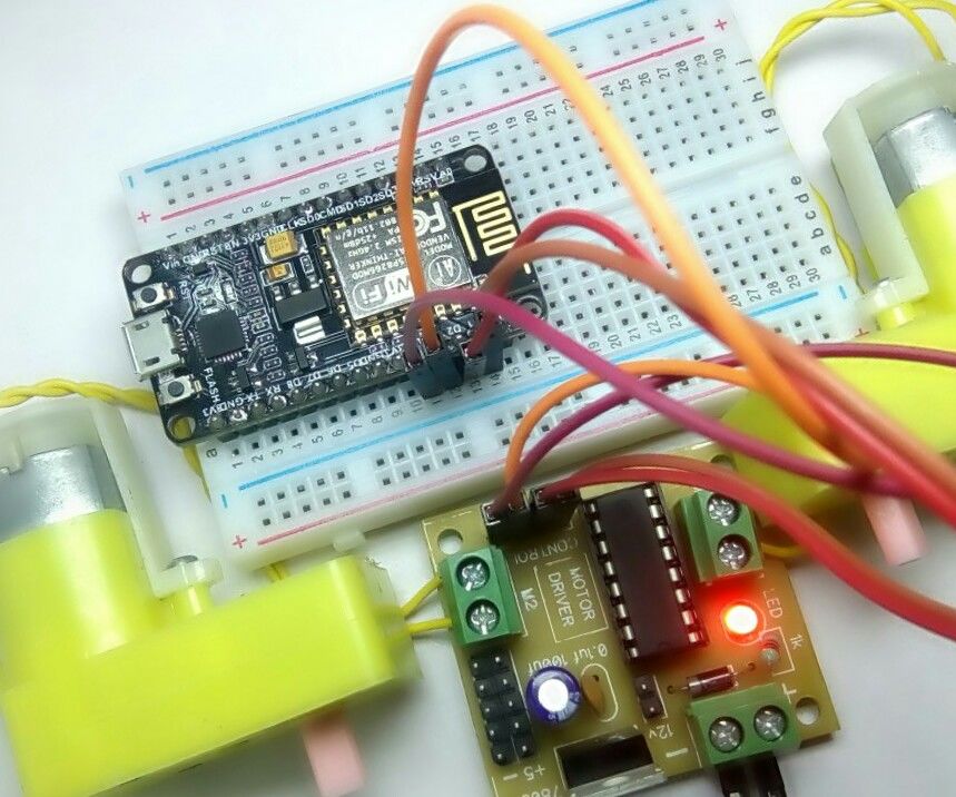
Step 2: The Circuit
The connections are easy, see the image above with the breadboard circuit schematic.
Step 4: Well Done!
You have successfully completed one more Arduino "How to" tutorial and you learned how to use the L293D motor driver IC to control two dc motors with the Arduino uno board.
How many volts does a L293D need?
Next, we need to supply 5 Volts for the L293D’s logic circuitry. Connect Vcc1 pin to 5V output on Arduino. Make sure you common all the grounds in the circuit.
What are the two types of control pins on a L293D?
For each of the L293D’s channels, there are two types of control pins which allow us to control speed and spinning direction of the DC motors at the same time viz. Direction control pins & Speed control pins.
What pins are used to control motor A and motor B?
The speed control pins viz. ENA and ENB are used to turn ON, OFF and control speed of motor A and motor B respectively.
How many voltages can you connect to a DC motor?
You can connect two DC motors having voltages between 4.5 to 36V to these terminals.
How many direction control pins are there in an IC?
The IC has two direction control pins for each channel. The IN1,IN2 pins control the spinning direction of the motor A while IN3,IN4 control motor B.
How many motors can a robot drive?
That means it can individually drive up to two motors making it ideal for building two-wheel robot platforms.
How to control DC motors?
One of the easiest and inexpensive way to control DC motors is to interface L293D Motor Driver IC with Arduino. It can control both speed and spinning direction of two DC motors.
What is a L293D IC?
L293d IC is known as a motor driver. It is a low voltage operating device like other ICs. The other ICs could have the same functions like L293d but they cannot provide the high voltage to the motor. L293d provides the continuous bidirectional Direct Current to the Motor.
How to use L293D?
L293d may have an internal complex circuit, but it is easy to use in real life. Just attach two motors with output pins. Remember at output 1 and output 2 same motor should be connected and it needs to be the same for output 3 and output 4. All ground should be common with both the power supplies provided to the IC. The enable pins are used to control the outputs but when we use the microcontrollers or microprocessor these enable pins can be used to control the speed of the motor.
Why we need a Motor Driver?
Every AC and DC motor have the ability to rotate in both directions. AC motor has its own rules and usage, but DC motor could rotate in another direction just by changing the polarity of the current. Now a day mostly DC Motors are used to produce rotatory motion due to its high efficiency. But in some cases, we need to rotate the motor in both directions. Like robots, cars, etc. There are multiple circuits by which motor could be rotated in both directions just by using some diodes and transistors. But those circuits are complex to make. To avoid the complexity and IC name l293d was invented by which not only direction, other multiple functions could be achieved just by the blink of an eye.
Who invented the DC motor?
After the invention of right-hand rule, a DC motor was invented by British scientist William Sturgeon. The DC motor was the first motor used by the scientist to convert the electric current to rotatory motion.
Can L293D be used without limitations?
As you read above L293d has multiple featured and usage where it can be used without any limitations. Here is an example of the circuit of street racing cars. We just need to use two L293d to control the car.

What Is A H-Bridge?
Inputs and Outputs
- There are two types of input to the L293D. Two pins are ‘enable’ pins as described above, while four are the inputs to actuate the ‘switches’. These actually control the base of internal NPN transistors, which activate internal constant current sources. These are fed to the base of darlington-arranged output transistor networks. On the L293D, the outputs have clamping diode…
Using The L293D
- The two most likely uses of the L293D for the maker are to drive two DC motors accurately, and to control bipolar stepper motors. The device is capable of controlling four DC motors in a single-direction format, where each is simply switched on or off, but MOSFET circuits seem to be the preference among makers for this. It could be used to drive fo...
Running Two DC Motors
- Using two DC motors together is often a feature of robotics projects. Whether using wheels or tracks, this format allows easy steering capability by varying the speed and/or direction of the motors, and eliminates the need for differential gears and drive trains. The system was used in early tanks, which had separate engines. Many modern tracked military vehicles, particularly ligh…
Stepper Motors
- Driving Bipolar stepper motors works in a very similar way, except that there are two windings in one motor, rather than one winding in each of two motors. Stepper motors have a permanent magnetic rotor and a series of coils as a stator, the reverse from a common DC motor. There will be many coils around the stator, but each alternate one is connected so that only two groups, or …
Output Current
- The limiting factor in the L293D is its current capacity. The maximum of 600mA continuous does not change with PWM situations. Remember, the 1.2A peak is only for one hundred microseconds, and is not repeatable in a short time frame. This really means your motor must be drawing well under 600mA in order to be used with the L293D. Unfortunately, things aren’t as simple as just b…
Other Uses
- The L293D is still valid for other uses, from RGB LED controllers as described by Sophie in Bridging the Gaps. Despite its current limit, the device can drive more than many general purpose transistors, and has the added benefits of outputs protected against inductive loads, along with versatile input configurations.
Test Platform Build
- * Quantity required, may only be sold in packs. # We used the chassis, but you could choose two suitable motors Note: Knobs are optional and are open to maker choice This relatively straightforward build is an expansion of Sophie’s design from Issue 012. We’re going to use an Arduino compatible Uno and the L293D to drive two motors, which run from 5V DC at 150mA to …
Assembly
- We used a motor chassis for our build, but you can just use two motors if you’re developing for a different physical application. If you are using a chassis, assemble it now. Solder any improvised heatsink you may be using to the relevant pins of the L293D, allow it to cool, then insert it into the board. Note that this heatsink is not included in the parts list, as you can use whatever you have …
Where to from Here?
- Our circuit cannot reverse or neutral turn as is. Neutral turning, also called zero turning, is where one motor moves forwards and the other backwards. This is better achieved with two potentiometers, one for each PWM pair of channels. Generally, the code would read each potentiometer. Both speed and direction are related to the 50% mark. Above 50% is forward and …