What is positive and negative clamper? If the circuit pushes the signal upwards then the circuit is said to be a positive clamper. When the signal is pushed upwards, the negative peak of the signal meets the zero level. On the other hand, if the circuit pushes the signal downwards then the circuit is said to be a negative clamper.
How do you know if a clamper is positive or negative?
Feb 09, 2020 · What is positive and negative clamper? If the circuit pushes the signal upwards then the circuit is said to be a positive clamper. When the signal is pushed upwards, the negative peak of the signal meets the zero level. On the other hand, if the circuit pushes the signal downwards then the circuit is said to be a negative clamper. Click to see full answer.
What is a positive clamper circuit?
If the circuit pushes the signal upwards then the circuit is said to be a positive clamper. When the signal is pushed upwards, the negative peak of the signal meets the zero level. On the other hand, if the circuit pushes the signal downwards then the circuit is said to be a negative clamper.
What are biased positive clampers?
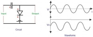
1. Positive Clamper . During the negative half cycle of the input signal, the diode conducts and acts like a short circuit. The output voltage V o 0 volts . The capacitor is charged to the peak value of input voltage Vm. and it behaves like a battery.During the positive half of the input signal, the diode does not conduct and acts as an open circuit.
What are the different types of negative clampers?
Negative Clamper. During the positive half cycle the diode conducts and acts like a short circuit. The capacitor charges to peak value of input voltage V m. During this interval the output V o which is taken across the short circuit will be zero. During the negative half cycle, the diode is open. The output voltage can be found by applying KVL. Biased Clamper
What is a positive clamper?
A Positive Clamper circuit is one that consists of a diode, a resistor and a capacitor and that shifts the output signal to the positive portion of the input signal. The figure below explains the construction of a positive clamper circuit.
What is clipper and clamper explain positive and negative?
A circuit which cutoff voltage above or below are both at specified level is called clipper. A clipper which removes a portion of positive half cycle of the input signal is called positive clipper. A clipper circuit that removes the negative half cycle is called negative clipper.
What is the function of clampers?
A clamper is an electronic circuit that fixes either the positive or the negative peak excursions of a signal to a defined value by shifting its DC value. The clamper does not restrict the peak-to-peak excursion of the signal, it moves the whole signal up or down so as to place the peaks at the reference level.
What is clamper circuit and its types?
Positive Clamper: This type of clamping circuit shifts the input waveform in a positive direction, as a result the waveform lies above a DC reference voltage. Negative Clamper: This type of clamping circuit shifts the input waveform in a negative direction, as a result the waveform lies below a DC reference voltage.Apr 29, 2021
What is clamper and clipper?
The major difference between clipper and clamper is that clipper is a limiting circuit which limits the output voltage while clamper is a circuit which shifts the DC level of output voltage. The clipper and clamper circuits are exactly opposite to each other regarding their working principle.
Where are clippers used?
A frequently used half-wave rectifier in power supply kits is a typical example of a clipper. It clips either positive or negative half-wave of the input. Clippers can be used as voltage limiters and amplitude selectors.
Why capacitors are used in clampers?
A capacitor is used to provide a dc offset (dc level) from the stored charge. A typical clamper is made up of a capacitor, diode, and resistor. Some clampers contain an extra element called DC battery. The resistors and capacitors are used in the clamper circuit to maintain an altered DC level at the clamper output.
What is a clamper?
: a patched-together argument or charge his defense was a mere clamper. clamper. noun (2) clamp·er | \ ˈklampə(r), -laam- \ plural -s.
What is diode clamper?
A clamper is an electronic circuit that prevents a signal from exceeding a certain defined magnitude by shifting its DC value. The clamper does not restrict the peak-to-peak excursion of the signal, but moves it up or down by a fixed value.
Why is clamper called DC inserter?
The DC level is added in the input signal that shifts the waveform to the desired level (upward or downward) without changing the width of the signal. It is called as DC inserter because it adds a DC voltage level to the output waveform. We can also say that clamper adds value to the Y-axis of the signal waveform.
What is positive shunt clipper?
Positive Shunt Clipper. A Clipper circuit in which the diode is connected in shunt to the input signal and that attenuates the positive portions of the waveform, is termed as Positive Shunt Clipper.
What is clamper circuit explain the positive and negative clamper circuit with waveforms and circuit diagrams?
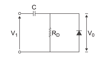
A clamper is circuit which is constructed of a diode, resistor and a capacitor that shifts a waveform to certain dc level without changing the appearance of applied signal. There are two types of clamper circuits: Positive Clamper. Negative Clamper.
What is a positive clamper?
The positive clamper with positive bias is made up of an AC voltage source, capacitor, diode, resistor, and dc battery. During positive half cycle: During the positive half cycle, the battery voltage forward biases the diode when the input supply voltage is less than the battery voltage.
When does a positive clamper pass the input signal to the output load?
So the positive clamper passes the input signal to the output load when the diode is reverse biased and blocks the input signal when the diode is forward biased. During the negative half cycle of the input AC signal, the diode is forward biased and hence no signal appears at the output.
What happens when a diode is reverse biased?
In reverse biased condition, the diode does not allow electric current through it. So the input current directly flows towards the output. When the negative half cycle begins, the diode is in the non-conducting state and the charge stored in the capacitor is discharged (released).
What happens to the capacitor during a positive half cycle?
During the positive half cycle of the input AC signal, the diode is forward biased and hence no signal appears at the output. In forward biased condition, the diode allows electric current through it. This current will flows to the capacitor and charges it to the peak value of input voltage in inverse polarity -Vm. As input current or voltage decreases after attaining its maximum value Vm, the capacitor holds the charge until the diode remains forward biased.
What is the difference between a clipper and a clamper?
The basic difference between the clipper and clamper is that the clipper removes the unwanted portion of the input signal whereas the clamper moves the input signal upwards or downwards.
What is a clamper capacitor?
A capacitor is used to provide a dc offset (dc level) from the stored charge. A typical clamper is made up of a capacitor, diode , and resistor. Some clampers contain an extra element called DC battery. The resistors and capacitors are used in the clamper circuit to maintain an altered DC level at the clamper output.
What is clamper in electrical?
A clamper is an electronic circuit that changes the DC level of a signal to the desired level without changing the shape of the applied signal. In other words, the clamper circuit moves the whole signal up or down to set either the positive peak or negative peak of the signal at the desired level.
What happens during a negative clamper?
2. Negative Clamper. During the positive half cycle the diode conducts and acts like a short circuit. The capacitor charges to peak value of input voltage Vm. During this interval the output Vo which is taken across the short circuit will be zero During the negative half cycle, the diode is open.
What happens during a positive half cycle?
During the positive half cycle the diode conducts and acts like a short circuit. The capacitor charges to peak value of input voltage Vm. During this interval the output Vo which is taken across the short circuit will be zero During the negative half cycle, the diode is open. The output voltage can be found by applying KVL.
What is positive clamping?
Positive clamping occurs when negative peaks raised or clamped to ground or on the zero level In other words, it pushes the signal upwards so that negative peaks fall on the zero level. Negative clamping occurs when positive peaks raised or clamped to ground or on the zero level In other words, it pushes the signal downwards ...
What is bias clamper?
A biased clamper means that the clamping can be done at any voltage level other than zero.
What is a clamping circuit?
A circuit that places either the positive or negative peak of a signal at a desired D.C level is known as a clamping circuit. A clamping circuit introduces (or restores) a D.C level to an A.C signal. Thus a clamping circuit is also known as D.C restorer, or D.C reinserted or a baseline stabilizer. The following are two general types of clamping.
What is clamper circuit?
Electronic Circuits - Clamper Circuits. A Clamper Circuit is a circuit that adds a DC level to an AC signal. Actually, the positive and negative peaks of the signals can be placed at desired levels using the clamping circuits. As the DC level gets shifted, a clamper circuit is called as a Level Shifter. Clamper circuits consist of energy storage ...
What happens to a capacitor during a negative half cycle?
During the negative half cycle, at the peak value, the capacitor gets charged with negative on one plate and positive on the other. The capacitor is now charged to its peak value V m. The diode is forward biased and conducts heavily.
Is the output voltage negative or positive?
Though the output voltage is negatively clamped, a portion of the output waveform is raised to the positive level, as the applied reference voltage is positive. During the positive half-cycle, the diode conducts, but the output equals the positive reference voltage applied.
Why is a negative clamper called a negative clamper?
When the positive cycle clamps/shifts below the zero voltage level, then the clamper circuit is called as Negative Clamper because the whole signal is shifted to the negative side. The circuit diagram to build an Negative clamper is shown below:
When the negative cycle clamps/shifts above the zero voltage level, then the clamper circuit is called as "
When the negative cycle clamps/shifts above the zero voltage level, then the clamper circuit is called as Positive Clamper because the whole signal is shifted to the positive side. It’s a really simple circuit to design, you just need to follow the circuit diagram below:
What is bias clamper?
A biased clamper is nothing different than positive and negative clampers discussed earlier. It just consists of a bias voltage with diode. So, if you connect the bias voltage with positive clamper then it just gets added with output voltage and it will shift to more positive level as the bias voltage. And if you connect the bias voltage ...
What is the difference between a clipper and a clamper?
The difference between a clipper and a clamper is that the clipper circuit changes the shape of the waveform but clamper just manipulates the DC level of output signal. While choosing the resistor and capacitor you must be aware about the discharging time of the capacitor as it maintains the time period of the waveform.
Why should an electrolytic capacitor not be used in clamper circuits?
The electrolytic capacitor should not be used in clamper circuits because they charge and discharge slowly. The discharging time () can be calculated using the below formula: t (Tau) = RC. Where R is the resistance used in the circuit and C is the capacitance of the capacitor. There are mainly three types of clamper circuits based upon the clamping:
Why does a negative bias voltage shift to a negative level?
But remember if you connect a negative bias voltage with positive clamper then instead of shifting to the positive level it will shift to some negative level because it will get subtracted from output voltage. And if you connect a positive bias voltage with negative clamper then instead of shifting to the negative level it will shift ...
What is a clipper circuit?
Previously we learned about Clipper Circuits, which are used to clip off the positive or negative part of the Alternating waveform. Today we will learn about Clamper circuits which are used to clamp the DC level of the output signal without distorting the waveform i.e. they are Level Shifter circuits. It can be designed using capacitor, diode and resistor. The difference between a clipper and a clamper is that the clipper circuit changes the shape of the waveform but clamper just manipulates the DC level of output signal.
What is a negative clamper?
Negative clamper circuits are used to add a negative clamping voltage to a signal. In essence, a negative clamper circuit decreases the central voltage level around which the sine wave oscillates.
What is clamper in AC?
A clamper is a circuit that adds a DC component to an AC signal. This can be used to set the levels of the positive and negative peaks of an AC waveform.
What is the time constant of a clamper circuit?
Like other RC circuits, clamper circuits feature a characteristic time constant ‘τ’, which is equal to value of the resistor times the value of the capacitor used in the clamper circuit:
What side of a capacitor will charge during the first positive half cycle?
The right side of the capacitor will charge during the first positive half cycle, while the diode is forward biased.
What is a clamper?
Clampers are also called direct current restorers as they clamp the waveforms to a fixed DC potential. These are frequently used in test equipment, sonar, and radar systems. For the protection of the amplifiers from large errant signals, clampers are used. Clampers can be used for removing the distortions.
What happens during a positive clipper?
During the positive half cycle, the diode becomes reverse-biased, and no output is generated across the resistor, and during the negative half cycle, the diode conducts and the entire input appears as output across the resistor .
What are the two types of clippers and clampers?
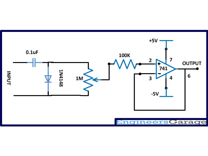
So, based on op-amp, clippers and clampers are mainly classified into two types and those are positive and negative types. Let us know the operation of clipper and clamper using op-amp.
What is the term for an electronic circuit that is used to alter the positive peak or negative peak of the input signal to
An electronic circuit that is used to alter the positive peak or negative peak of the input signal to a definite value by shifting the entire signal up or down to obtain the output signal peaks at the desired level is called a Clamper circuit . There are different types of clippers and clampers circuits as discussed below.
What is a series positive reference voltage?
A series positive reference voltage is added to the diode as shown in the figure. During the positive half cycle, the input is generated as output, and during the negative half cycle, a positive reference voltage will be the output voltage as shown below.
What are clipper circuits?
The clipper circuit can be designed by utilizing both the linear and nonlinear elements such as resistors, diodes, or transistors. As these circuits are used only for clipping input waveform as per the requirement and for transmitting the waveform, they do not contain any energy storing element like a capacitor.
Which side of a diode receives a negative voltage?
In the same way, the anode side of the D2 diode is connected to negative DC voltage and the cathode side receives a varied negative voltage.