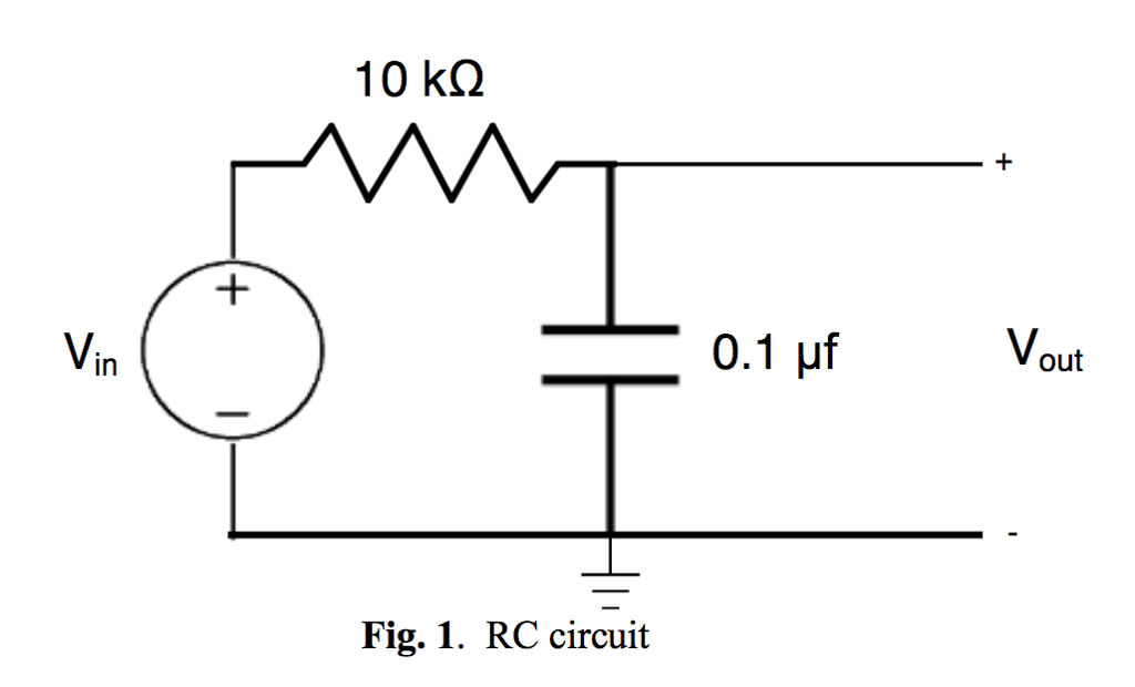
The RC time constant
RC time constant
The RC time constant, also called tau, the time constant (in seconds) of an RC circuit, is equal to the product of the circuit resistance (in ohms) and the circuit capacitance (in farads), i.e. It is the time required to charge the capacitor, through the resistor, by ≈ 63.2 percent of the difference between the initial value and final value or discharge the capacitor to ≈36.8 percent.
What does a high time constant for RC circuit mean?
High RC time constant leads to a lower ripple of the output voltage around its average value. #1 is easy to explain - just recall that high time constant means longer raise/fall time of the voltage in a simple RC circuit. The same applies to this RC filter.
What is the definition of the time constant for a RC circuit?
The RC time constant , also called tau, the time constant (in seconds) of an RC circuit , is equal to the product of the circuit resistance (in ohms) and the circuit capacitance (in farads), i.e. τ = R C {\displaystyle \tau = RC }.
What is the formula for time constant?
RC Charging Circuit Example No1. Calculate the RC time constant, τ of the following circuit. The time constant, τ is found using the formula T = R x C in seconds. Therefore the time constant τ is given as: T = R x C = 47k x 1000uF = 47 Secs.
How to find time constant?
The time you go to sleep, however, might vary, depending on any number of things:
- your social life
- your work schedule
- family obligations
- the newest show streaming on Netflix
- the time you start to feel tired

What is the use of time constant?
what is the use of time constant? The time constant is also used to characterize the frequency response of various signal processing systems – magnetic tapes, radio transmitters and receivers, record cutting and replay equipment, and digital filters – which can be modeled or approximated by first-order LTI systems.
What is the time constant of a capacitor?
In RC (resistive & capacitive) circuits, time constant is the time in seconds required to charge a capacitor to 63.2% of the applied voltage. This period is referred to as one time constant. After two time constants, the capacitor will be charged to 86.5% of the applied voltage.
Is time constant or relative?
There is no unit of time constant, because we don't time at a constant speed. Time is relative. The closest you can get is to use “the rate at which a stationary object times, on earth, at sea level, on the equator” as a baseline, and compare other rates to it.
What is the time constant in a circuit?
This delay is generally known as the circuits time delay or Time Constant which represents the time response of the circuit when an input step voltage or signal is applied. The resultant time constant of any electronic circuit or system will mainly depend upon the reactive components either capacitive or inductive connected to it. Time constant has units of, Tau – τ
How to find time constant?
The time constant, τ is found using the formula T = R x C in seconds .
How many time constants does a capacitor need to charge?
The time required for the capacitor to be fully charge is equivalent to about 5 time constants or 5T. Thus, the transient response or a series RC circuit is equivalent to 5 time constants.
Why is the RC charging curve steeper?
The rise in the RC charging curve is much steeper at the beginning because the charging rate is fastest at the start of charge but soon tapers off exponentially as the capacitor takes on additional charge at a slower rate.
What is the time period after 5T?
The time period after this 5T time period is commonly known as the Steady State Period .
How to measure transient response time?
This transient response time T, is measured in terms of τ = R x C, in seconds, where R is the value of the resistor in ohms and C is the value of the capacitor in Farads. This then forms the basis of an RC charging circuit were 5T can also be thought of as “5 x RC”.
What is time delay in electrical circuits?
All Electrical or Electronic circuits or systems suffer from some form of “time-delay” between its input and output terminals when either a signal or voltage, continuous, ( DC ) or alternating ( AC ), is applied to it.
