In a series RC circuit
RC circuit
A resistor–capacitor circuit (RC circuit), or RC filter or RC network, is an electric circuit composed of resistors and capacitors driven by a voltage or current source. A first order RC circuit is composed of one resistor and one capacitor and is the simplest type of RC circuit.
Alternating current
Alternating current is an electric current which periodically reverses direction, in contrast to direct current which flows only in one direction. Alternating current is the form in which electric power is delivered to businesses and residences, and it is the form of electrical energy that consu…
How to calculate the alternating current in a series RC circuit?
In a series RC circuit connected to an AC voltage, the alternating currentthrough the resistor and the capacitor are the same. The AC voltage VS is equal to the phasor addition of the voltage drop across the resistor (Vr) and the voltage drop across the capacitor (Vc). See the following formula: Vs = Vr + Vc.
How does a series RC circuit work?
How a series RC circuit work? In a series RC circuit connected to an AC voltage, the alternating currentthrough the resistor and the capacitor are the same. The AC voltage VS is equal to the phasor addition of the voltage drop across the resistor (Vr) and the voltage drop across the capacitor (Vc).
How current leads the supply voltage in an R-C circuit?
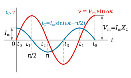
Thus in an R-C series circuit current leads the supply voltage by an angle The voltage and current waveforms of the R-C series circuit are shown in fig. The instantaneous value of the power is the product of the instantaneous values of the voltage and current.
What is the phase angle of a series RC circuit?
The applied source voltage and current will be out of phase by some amount between 0 and 90 degrees. The size of the phase angle will be determined by the ratio between resistance and capacitance. The series RC circuit vector is similar to the RL circuit in that it uses the common current element as the reference vector.
What is a phase relationship between voltage and current in series RC circuit?
The phase difference is <= 90 degrees. It is customary to use the angle by which the voltage leads the current. This leads to a positive phase for inductive circuits since current lags the voltage in an inductive circuit. The phase is negative for a capacitive circuit since the current leads the voltage.
What is the relation of currents in a RC series circuit?
The current as a function of time can be found by taking the time derivative of the charge: I(t)=−QRCe−t/τ. The negative sign shows that the current flows in the opposite direction of the current found when the capacitor is charging.
What is the relationship between voltage and current as a capacitor in an RC circuit discharges?
The voltage across the capacitors plates is equal to the supply voltage and VC = VS. As the voltage at t = 0 across the capacitors plates is at its highest value, maximum discharge current therefore flows around the RC circuit.
What happens in RC series circuit?
A circuit that contains pure resistance R ohms connected in series with a pure capacitor of capacitance C farads is known as RC Series Circuit. A sinusoidal voltage is applied and current I flows through the resistance (R) and the capacitance (C) of the circuit.
Why current leads voltage in RC circuit?
Leading current In circuits with primarily capacitive loads, current leads the voltage. This is true because current must first flow to the two plates of the capacitor, where charge is stored. Only after charge accumulates at the plates of a capacitor is a voltage difference established.
How do you find the voltage in a RC circuit?
1:527:27RC Circuit Analysis (1 of 8) Voltage and Current - YouTubeYouTubeStart of suggested clipEnd of suggested clipAnd the voltage is equal to the current times the resistance. And that means that the voltage isMoreAnd the voltage is equal to the current times the resistance. And that means that the voltage is equal to 0.75.
What is the relation between current and voltage in capacitor?
To put this relationship between voltage and current in a capacitor in calculus terms, the current through a capacitor is the derivative of the voltage across the capacitor with respect to time. Or, stated in simpler terms, a capacitor's current is directly proportional to how quickly the voltage across it is changing.
What is the relationship between current and voltage in a capacitive circuit?
Alternating current in a simple capacitive circuit is equal to the voltage (in volts) divided by the capacitive reactance (in ohms), just as either alternating or direct current in a simple resistive circuit is equal to the voltage (in volts) divided by the resistance (in ohms).
What happens to the current and voltage in the capacitor at steady state?
The circuit is at steady state when the voltage and the current reach their final values and stop changing. In steady state, the capacitor has a voltage across it, but no current flows through the circuit: the capacitor acts like an open circuit.
How does the current in an RC circuit vary when the charge on the capacitor builds up?
As the charge on the capacitor increases, the current through the resistor decreases, as shown in (Figure)(b). The current through the resistor can be found by taking the time derivative of the charge.
What is effect of current in a RC parallel circuit?
In a parallel RC circuit, the line current leads the applied voltage by some phase angle less than 90 degrees but greater than 0 degrees. The exact angle depends on whether the capacitive current or resistive current is greater.
What is the relationship between time constant resistance and capacitance?
The RC time constant, also called tau, the time constant (in seconds) of an RC circuit, is equal to the product of the circuit resistance (in ohms) and the circuit capacitance (in farads), i.e.
What is RC series circuit?
A circuit that contains pure resistance R ohms connected in series with a pure capacitor of capacitance C farads is known as RC Series Circuit. A sinusoidal voltage is applied and current I flows through the resistance (R) and the capacitance (C) of the circuit.
Is the net power over a complete cycle positive?
Since the area under the positive loops is greater than that under the negative loops, therefore the net power over a complete cycle is positive.
What is RC Circuit?
A resistor-capacitor combination (sometimes called an RC filter or RC network) is a resistor-capacitor circuit. An RC circuit is an electrical circuit that is made up of the passive circuit components of a resistor (R) and a capacitor (C) and is powered by a voltage or current source.
RC Charging Circuit
A capacitor (C) in series with a resistor (R) forms an RC Charging Circuit that is connected across a DC battery supply (Vs) via a mechanical switch in the diagram below. When the switch is first closed at time zero, the capacitor progressively charges up through the resistor until the voltage across it reaches the battery’s supply voltage.
The Working Theory of an RC Coupled Amplifier in Electronics
Amplification is the technique of boosting a signal’s strength by raising its amplitude without changing its properties. An RC coupled amplifier is a component of a multistage amplifier that connects several stages of amplifiers using a resistor and a capacitor. One of the most fundamental circuits in electronics is the amplifier.
Steps To Draw a Phasor Diagram for an RC Circuit
Current I is considered as reference and voltage reduction in resistance is (V R ). So, V R = IR is drawn in phase with the current I. Voltage reduction in capacitive reactance is (V C ). As a result, V C = IX C (where X C is 1/2πfc) and is drawn 90 degrees behind the current (in a pure capacitive load circuit, current leads voltage by 90 degrees).
Why does an RC circuit consume energy?
Due to the presence of a resistor in the ideal form of the circuit, an RC circuit will consume energy, akin to an RL circuit or RLC circuit. This is unlike the ideal form of an LC circuit, which will consume no energy due to the absence of a resistor.
What is the difference between voltage drops in parallel R-C circuits?
Voltage drops in a parallel RC circuit are the same hence the applied voltage is equal to the voltage across the resistor and voltage across the capacitor. Current in a parallel R-C circuit is the sum of the current through the resistor and capacitor.
What happens if a capacitor is disconnected from the battery?
If fully charged capacitor is now disconnected from the battery supply voltage, the stored energy in the capacitor during the charging process would stay indefinitely on its plates, keeping the voltage stored across its terminals at a constant value.
Why is a capacitor drawn in phase with current?
is drawn in phase with current because in a pure resistor the voltage and current are in phase with each other. is drawn lagging with current by because in a pure capacitor voltage and current are out of each other i.e. voltage lags current by or current leads the voltage by . Now is the vector sum of and .
How does a capacitor work in a R-C circuit?
The figure shows the simple R-C circuit in which capacitor (C), in series with a resistor (R) that is connected to the DC voltage source via a mechanical switch (K). The capacitor is initially uncharged. When switch K is closed, the capacitor will gradually charge up through the resistor until the voltage across the capacitor becomes equal to the supply voltage source. The charge on the plates of the capacitor is given as Q = CV.
What is the response to a switch?
When something changes in a circuit, as a switch closes, the voltage and current also change and adjust to the new conditions. If the change is an abrupt step the response is called the step response.
Can a capacitor change voltage?
i.e., In the case of a capacitor, the voltage across the capacitor cannot be changed instantaneously.
Capacitor lags current in series RC circuit
Capacitor opposes sudden voltage changes, so the voltage in the capacitor is delayed with respect to the current flowing through it. The maximum voltage in the capacitor occurs 90° after the maximum current value. These 90° are equal to ¼ wavelength, given by the frequency of the current passing through the circuit.
How is the formula used?
The impedance value (Z), is obtained dividing the voltage Vs and current I. The angle (Φ) is obtained subtracting angle of “I” – angle “Vs”.
What is RC circuit?
RC circuit. The simplest RC circuit consists of a resistor and a charged capacitor connected to one another in a single loop, without an external voltage source. Once the circuit is closed, the capacitor begins to discharge its stored energy through the resistor.
What is required to synthesise an RC circuit?
To synthesise as an RC circuit, all the critical frequencies ( poles and zeroes) must be on the negative real axis and alternate between poles and zeroes with an equal number of each. Further, the critical frequency nearest the origin must be a pole, assuming the rational function represents an impedance rather than an admittance.
What are the components of an analog circuit?
There are three basic, linear passive lumped analog circuit components: the resistor (R), the capacitor (C), and the inductor (L). These may be combined in the RC circuit, the RL circuit, the LC circuit, and the RLC circuit, with the acronyms indicating which components are used. These circuits, among them, exhibit a large number of important types of behaviour that are fundamental to much of analog electronics. In particular, they are able to act as passive filters. This article considers the RC circuit, in both series and parallel forms, as shown in the diagrams below.
What is the impulse response of a circuit?
The impulse response for each voltage is the inverse Laplace transform of the corresponding transfer function. It represents the response of the circuit to an input voltage consisting of an impulse or Dirac delta function .
What is sinusoidal steady state?
Sinusoidal steady state is a special case in which the input voltage consists of a pure sinusoid (with no exponential decay). As a result,#N#σ = 0 {displaystyle sigma =0}#N#and the impedance becomes
What is RC filter?
A resistor–capacitor circuit ( RC circuit ), or RC filter or RC network, is an electric circuit composed of resistors and capacitors. It may be driven by a voltage or current source and these will produce different responses.
Is parallel RC circuit a series circuit?
The parallel RC circuit is generally of less interest than the series circuit. This is largely because the output voltage Vout is equal to the input voltage Vin — as a result, this circuit does not act as a filter on the input signal unless fed by a current source .
Apparatus
Resistor, Capacitor, AC power source, ammeter, voltmeter, connection wire etc..
Theory
When we apply an ac voltage to a resistor and capacitor in series, as shown in the schematic diagram below, the capacitor will constantly charge and discharge as the input voltage is constantly changing. Essentially, R and C in this circuit now form a voltage divider for ac.
How does a capacitor voltage work in RC circuits?
As with the RL Circuit, the behavior of an RC circuit can be represented graphically by plotting instantaneous current and voltage versus time. because energy is stored in a charged capacitor, a large current can flow when the capacitor terminals are short-circuited.
Is a capacitor static or dynamic?
The capacitor is able to hold its charge as a static quantity, and its terminal voltage is constant. This contrasts with the case of an inductor, where the charge is a dynamic quantity that cannot be maintained when the current is interrupted.